WRITE-UP : JL WRANGLER 2.5" EVO Stage 4 Boost Lift & Control Arms INSTALLATION
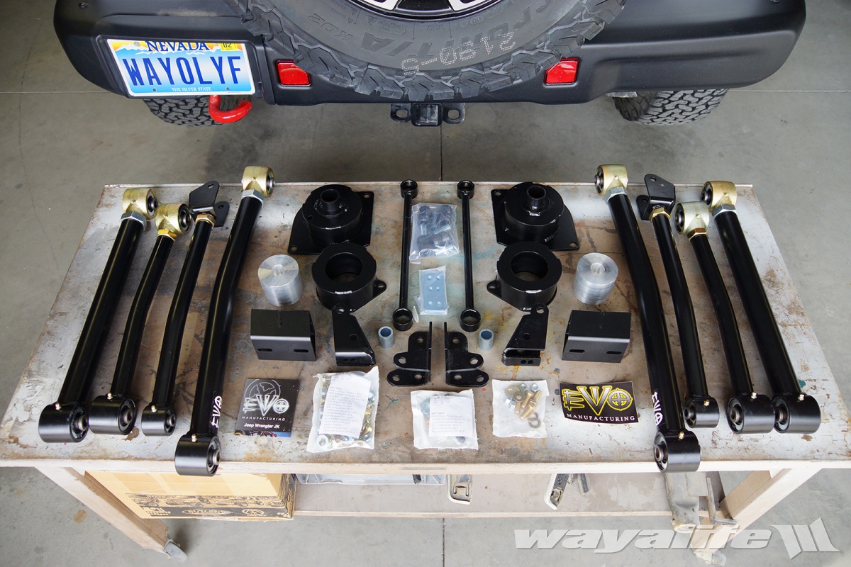
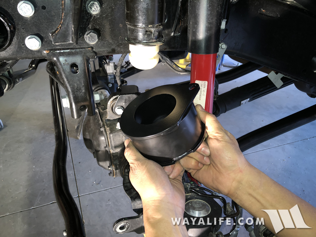
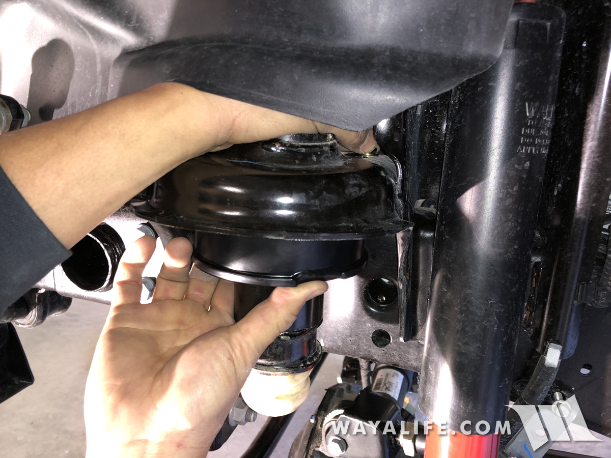
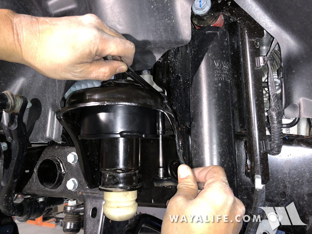
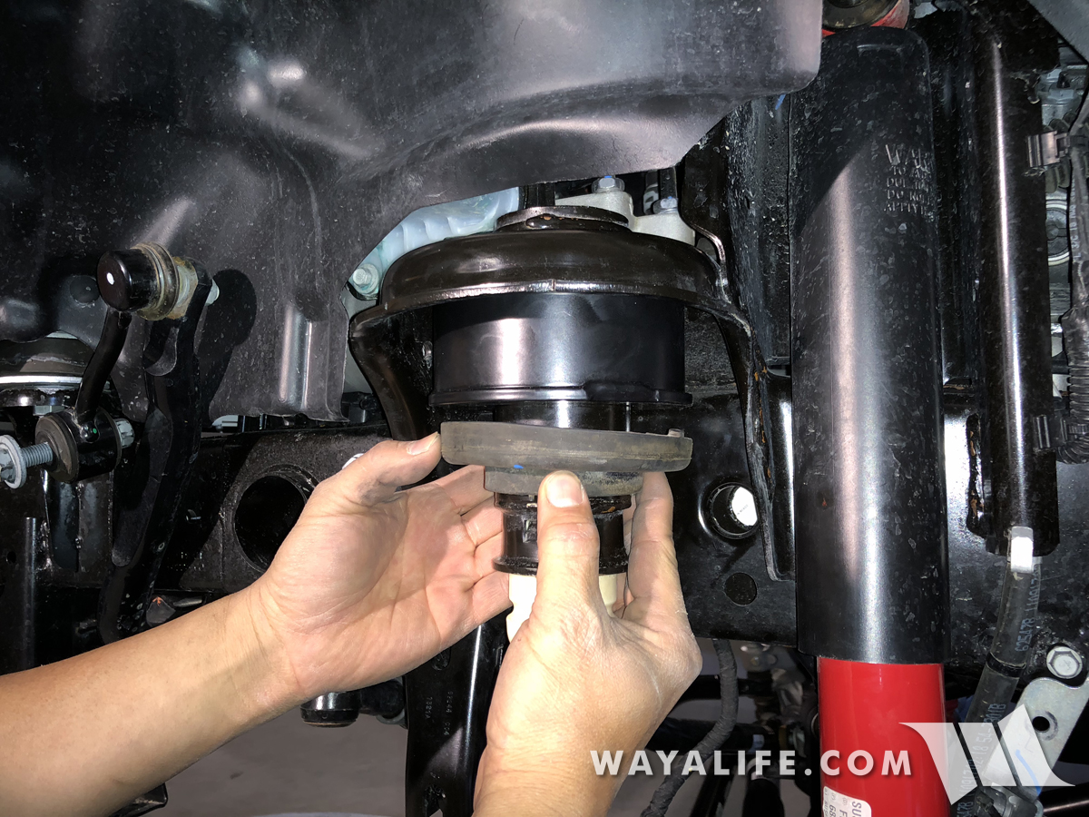
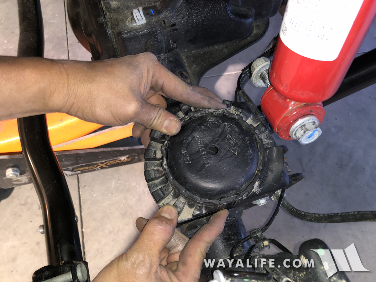
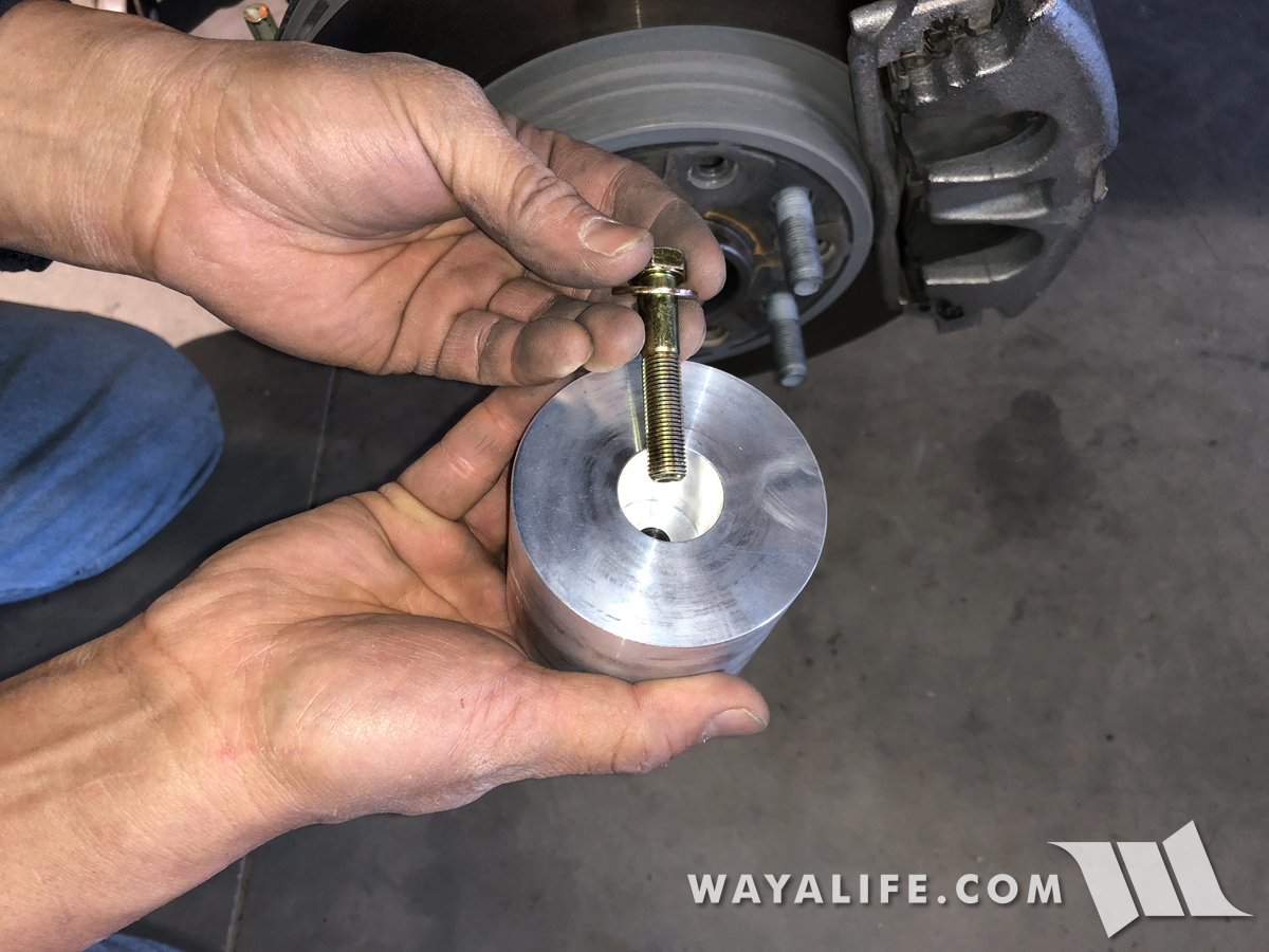
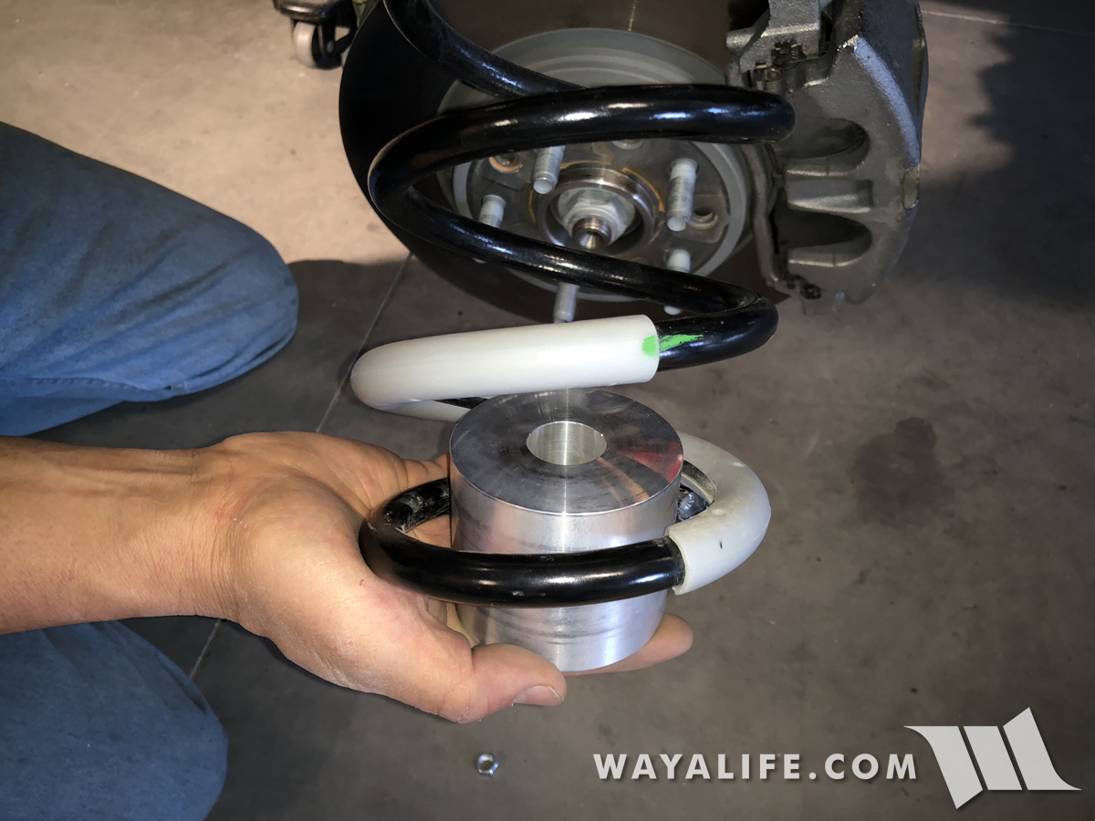
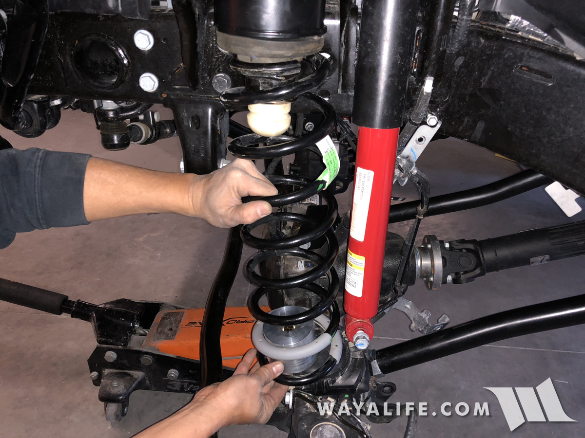
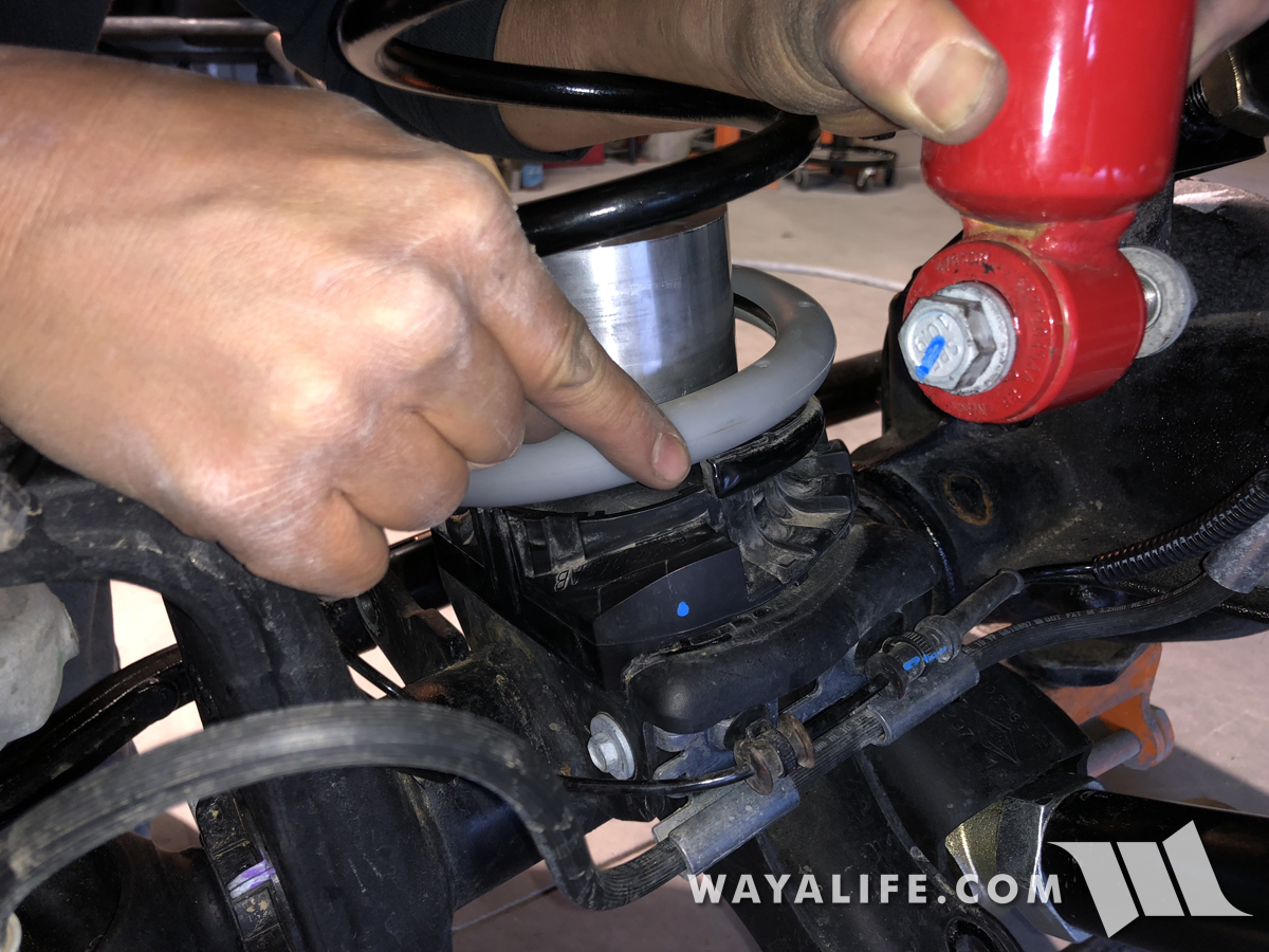
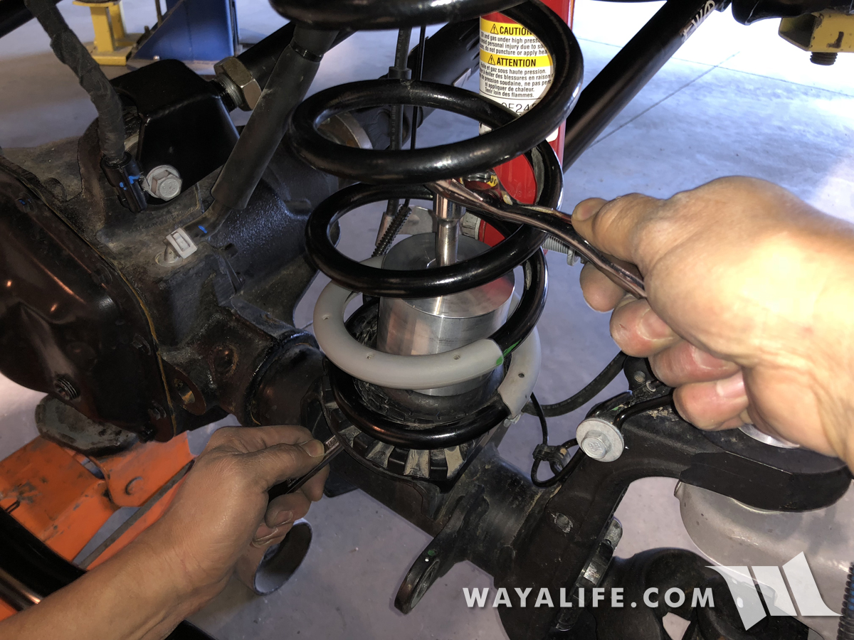
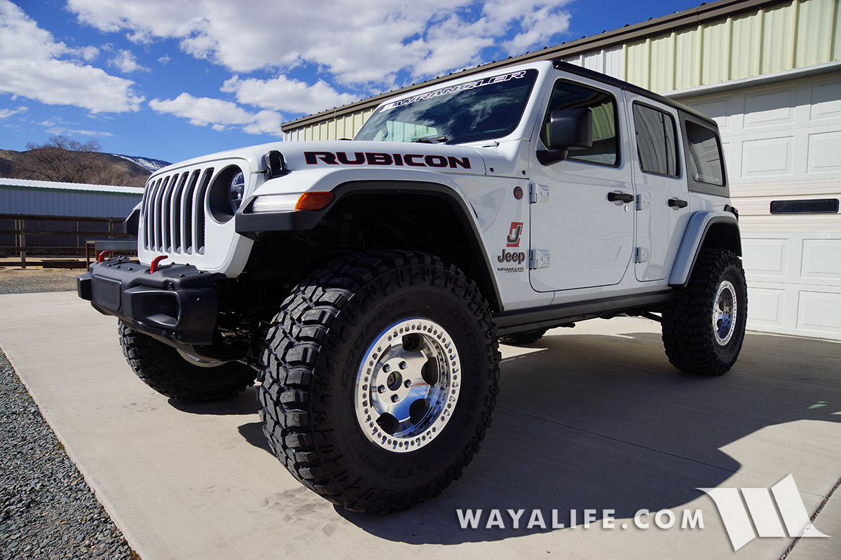
If you've got a Jeep JL Wrangler and are wanting to install a small lift on it, this installation write-up will show you just how easy it is to do. For our purposes, Cindy and I decided to get an EVO 2.5" Stage 4 Boost Lift or 'coil spacer lift', as it comes complete with 2.5" coil spacers, bump stop extensions, shock relocation brackets, a new pair of rear sway bar links and front brake line extension brackets. Basically, everything you'd need to run a set of 35" tires on a Sport or Sahara or 37" tires on a Rubicon. Being that we are anticipating making more changes in the future, we also decided to get the 8 heavy duty adjustable control arms that are offered as an option as well. With all that said, the instruction you'll find on this write-up will pretty much be the same for most any lift kit of this size and/or type and should still be helpful regardless of which one you get.
What You will get with the EVO Stage 4 Boost Lift
• (2) 2.5" Front Coil Spacers
• (2) 2.5" Rear Coil Spacers
• (2) Front Bumpstop Extensions
• (2) Rear Bumpstop Extensions
• (2) Front Shock Relocation Brackets
• (2) Rear Shock Relocation Brackets
• (2) Front Brake Line Extension Brackets
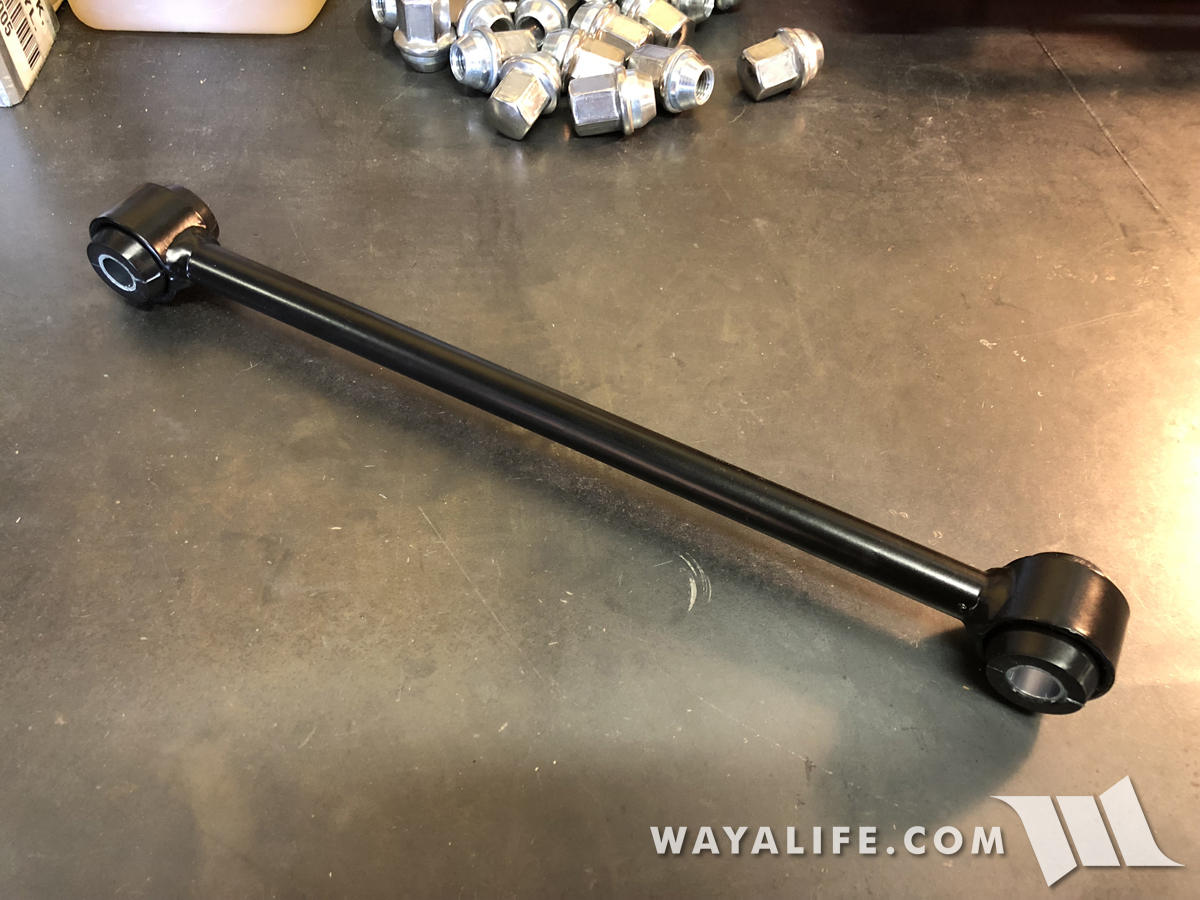
• (2) Rear Sway Bar Links
• Installation Hardware
Optional Components
• (2) Front Adjustable Lower Control Arms
• (2) Front Adjustable Upper Control Arms
• (2) Rear Adjustable Lower Control Arms
• (2) Rear Adjustable Upper Control Arms
What You Will Need
• 8, 10, 13, 15, 18, 19, 21, 22, 24mm Sockets & Wrenches
• 7/16, 1/2, 9/16, 5/8, 3/4" Sockets & Wrenches
• 1-1/2, 1-7/8" Wrenches
• Large Crescent Wrench
• Ratchet
• Short Ratchet Extension
• Long Ratchet Extension
• Ft. Lb. Torque Wrench
• Vicegrips
• Floor Jack
• Jack Stands
• Pry Bar
• Hand Drill
• Unibit or Metal Drilling Bits
• Cutting Oil
• Trim Pry Tool
• Dykes
• Hammer
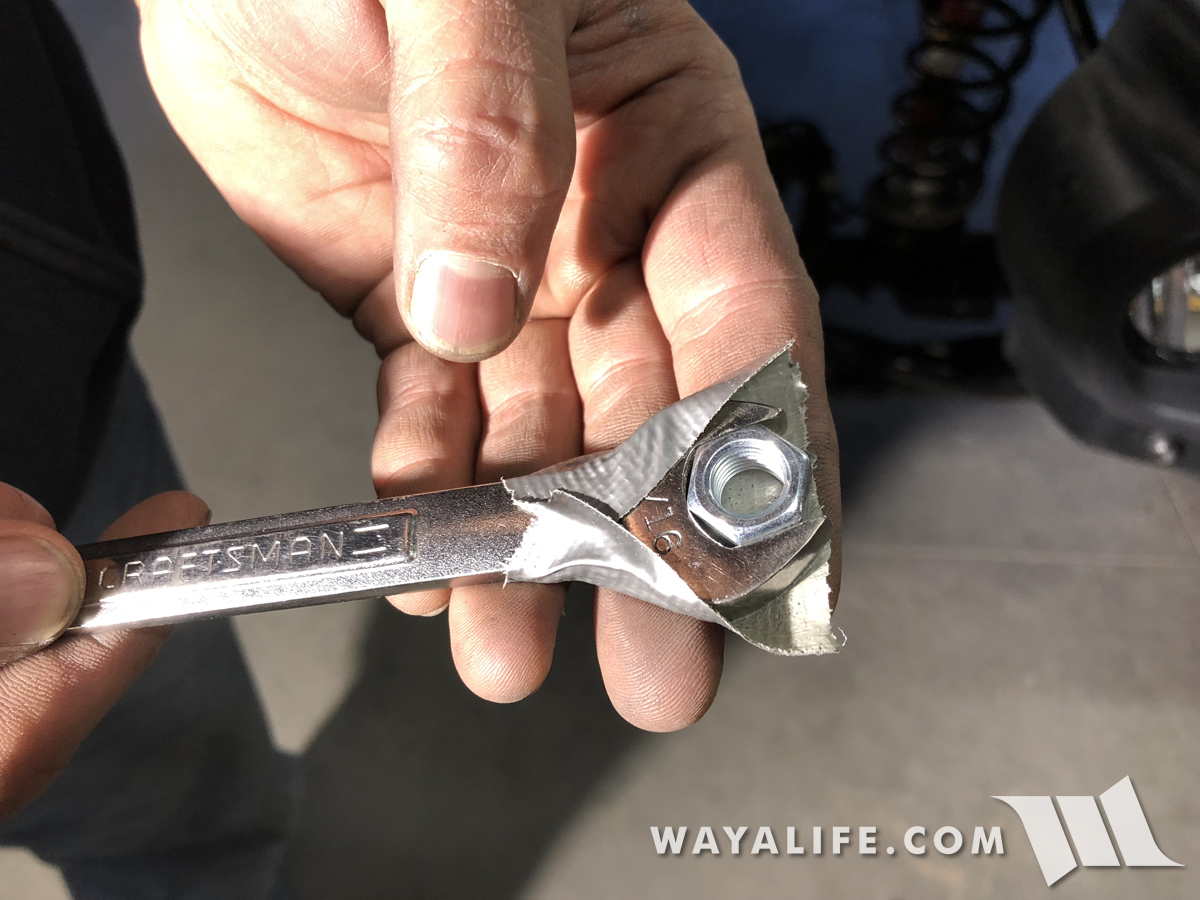
• Duct Tape
• Antiseize
• White Lithium Grease
Preparing the Optional EVO Adjustable Control Arms
If you purchased any or all the heavy duty adjustable control arms that EVO offers as an options, the following information will help you to set them up and get them ready for installation.
1. To begin, take a control arm and remove the adjustable Johnny Joint from it.
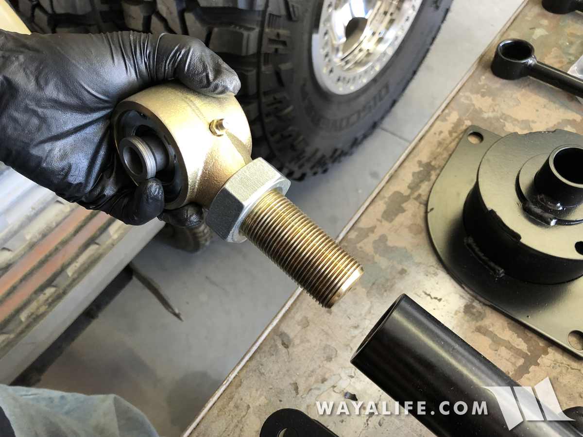
2. Rotate the jam nut down a bit, apply antiseize to the threads and then work it in by rotating the jam up and down through it.
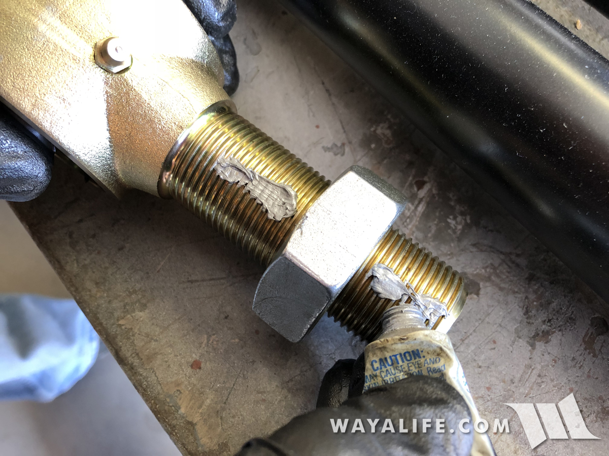
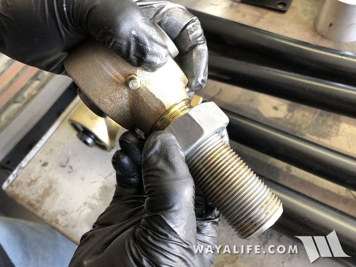
3. Reinstall the Johnny Joint and repeat Steps 1-2 on all the other control arms you got with your kit.
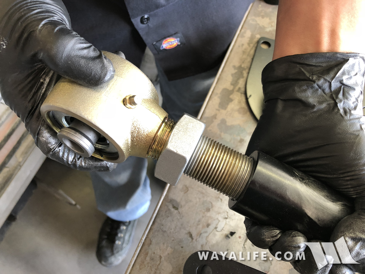
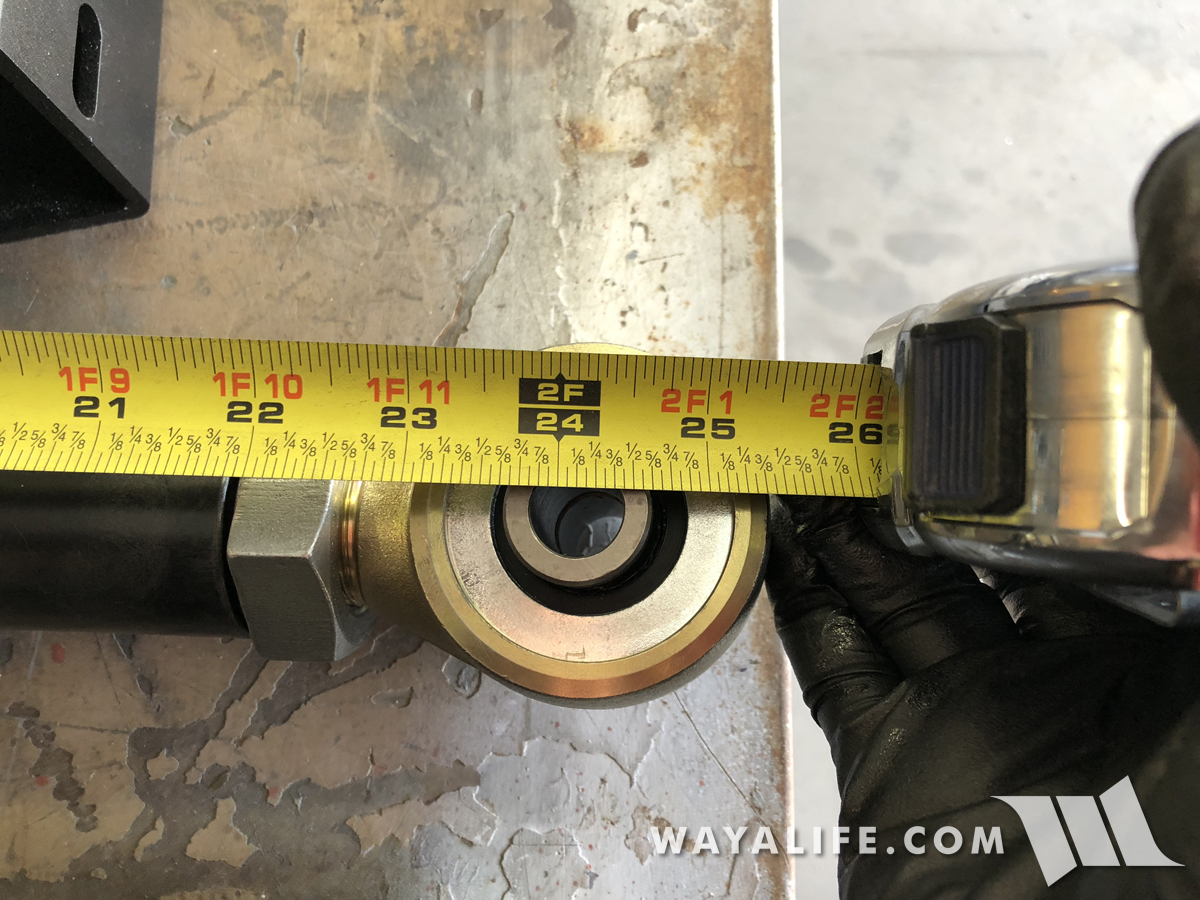
4. The length of the control arms will all need to be set. EVO does provides measurements for this but it should be noted that these are just starting points and addition adjustments may be required. To begin, take the front lower control arms and set them to 24-1/8" measuring from eye to eye (center of bolt hole to center of bolt hole).
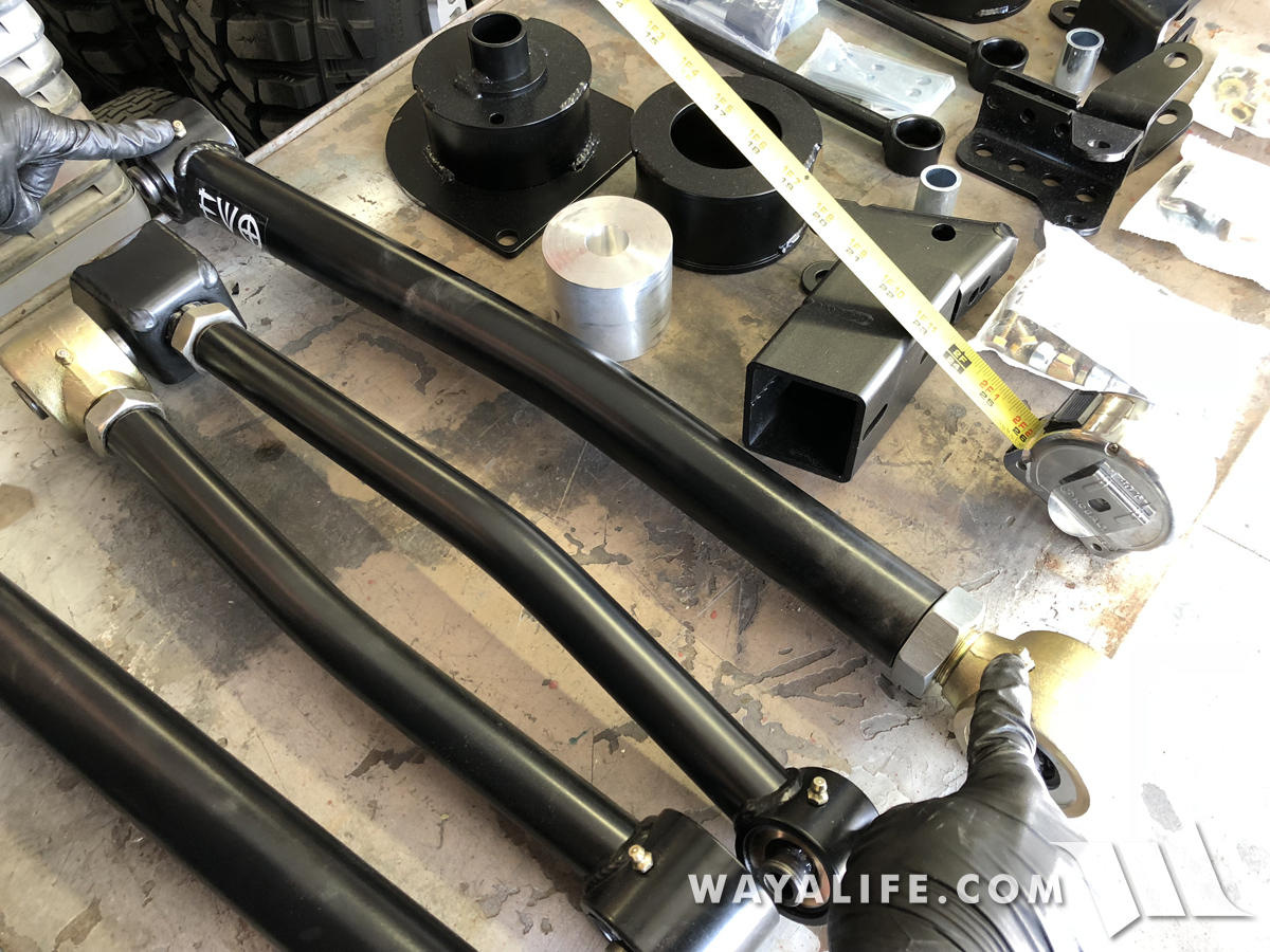
5. When the control arm is set to the proper length, both zerk nipples should be pointing in the same direction as can be seen in this photo.
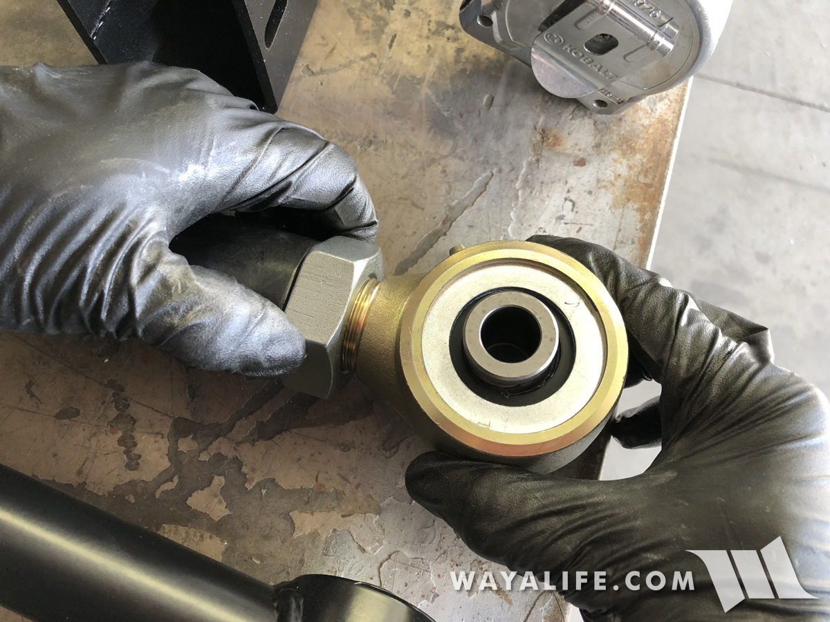
6. With the control arm set, tighten the jam nut by hand just to keep things in place.
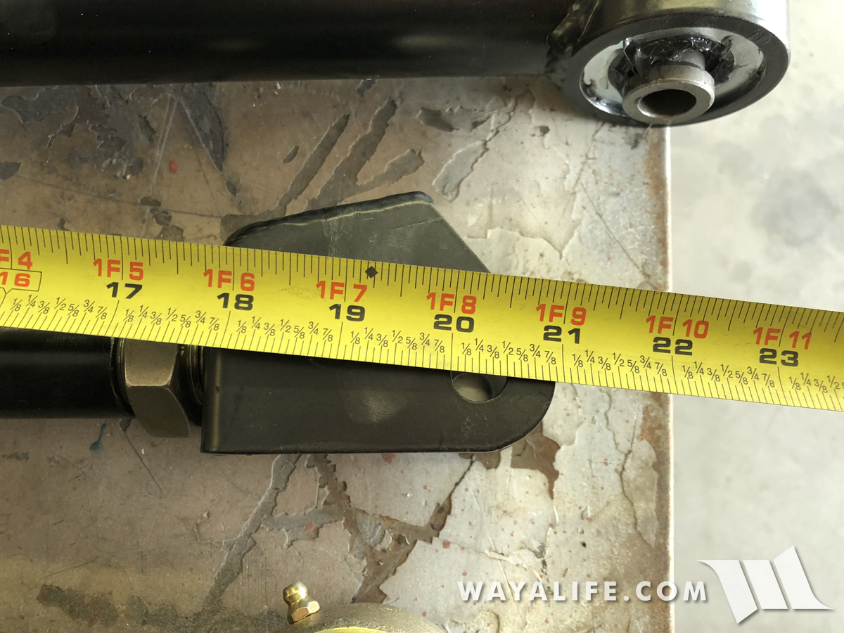
7. Being that the front axle has bushings pressed into the upper control arm mounts, the adjustable front upper arms will have forks instead of Johnny Joints. Again, as an initial starting point and measuring from eye to eye, set these arms to 20-1/4". You'll want to make sure that the open end of the fork is facing the same direction as the zerk nipple on the opposite end. Once set, tighten the jam nut by hand for now.
8. Measuring from eye to eye, the adjustable rear lower control arms should be set to 19-3/4". Again, double check to make sure both zerks are pointing the same direction when set and hand tighten the jam nuts for now.
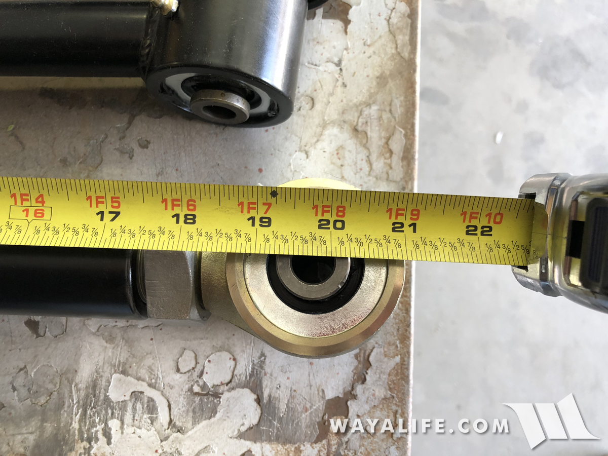
9. Last but not least, set the adjustable rear upper control arms to 17-1/2" measuring from eye to eye. Verify that the zerks are pointing in the same direction and then hand tighten the jam nut.
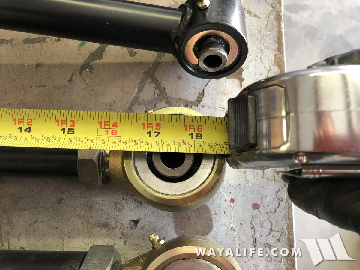
You're control arms should now all be set and ready to be installed.
Front Installation Instructions
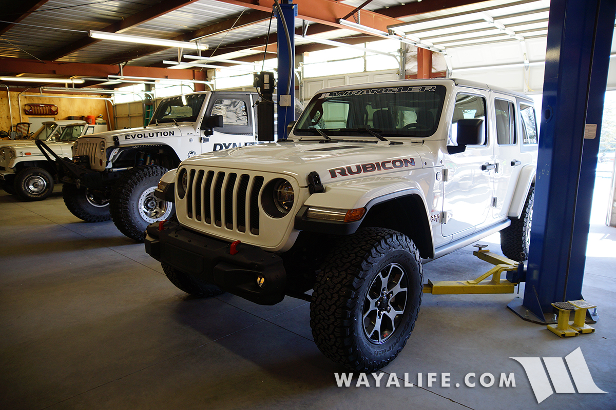
1. Unless you have a lift, you'll need to start this install by parking your Jeep JL Wrangler on a level ground, apply your parking brake and chock your rear tires.
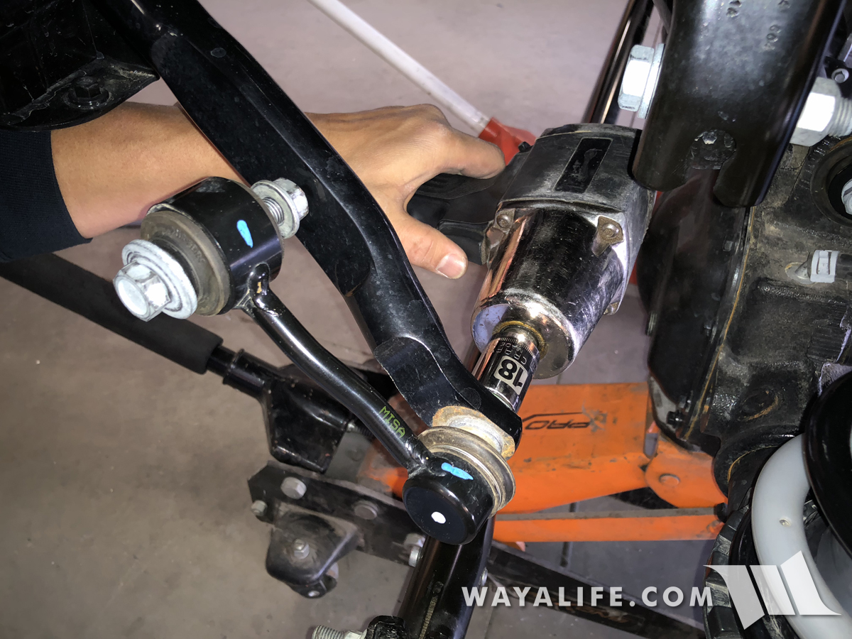
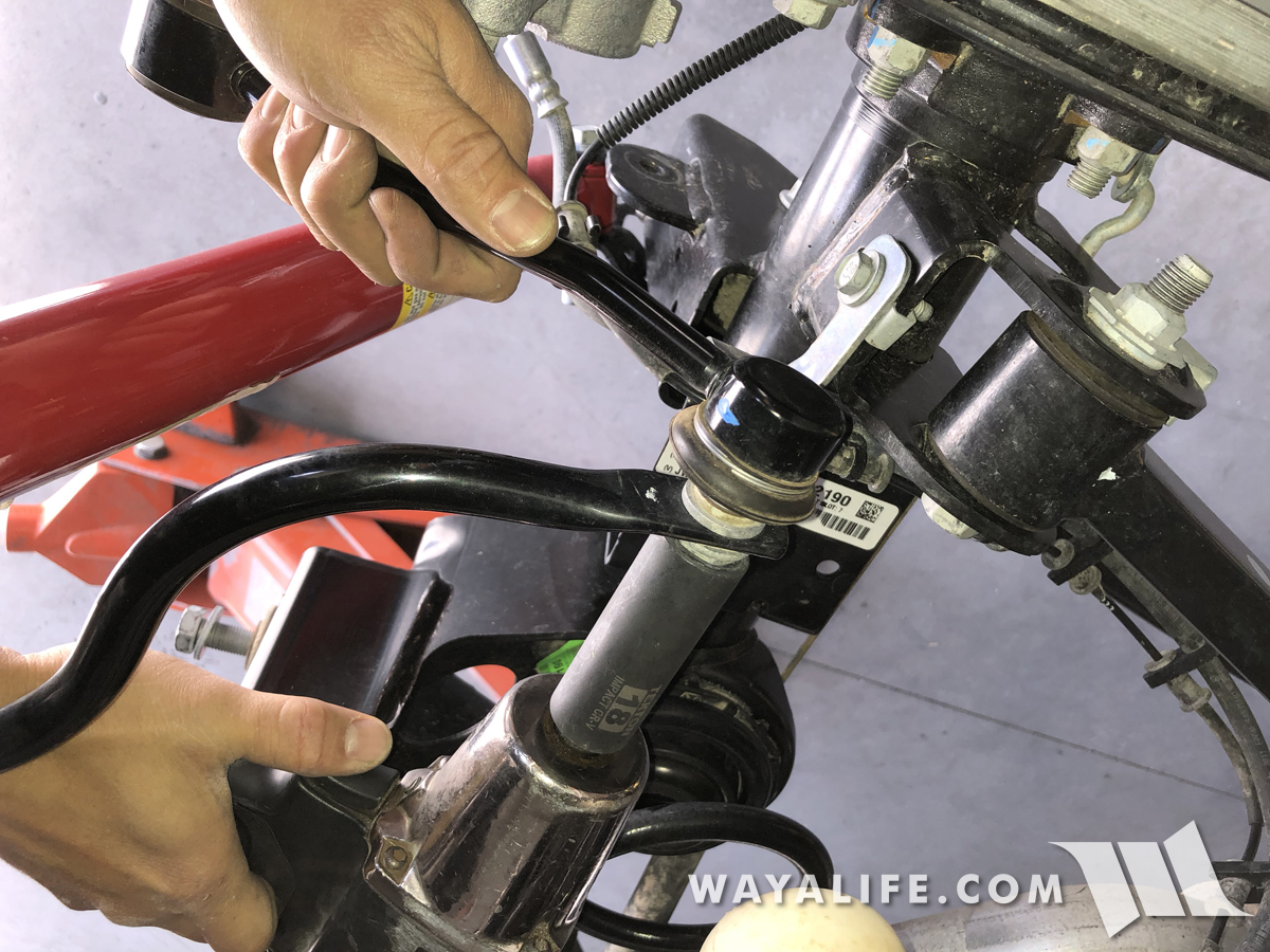
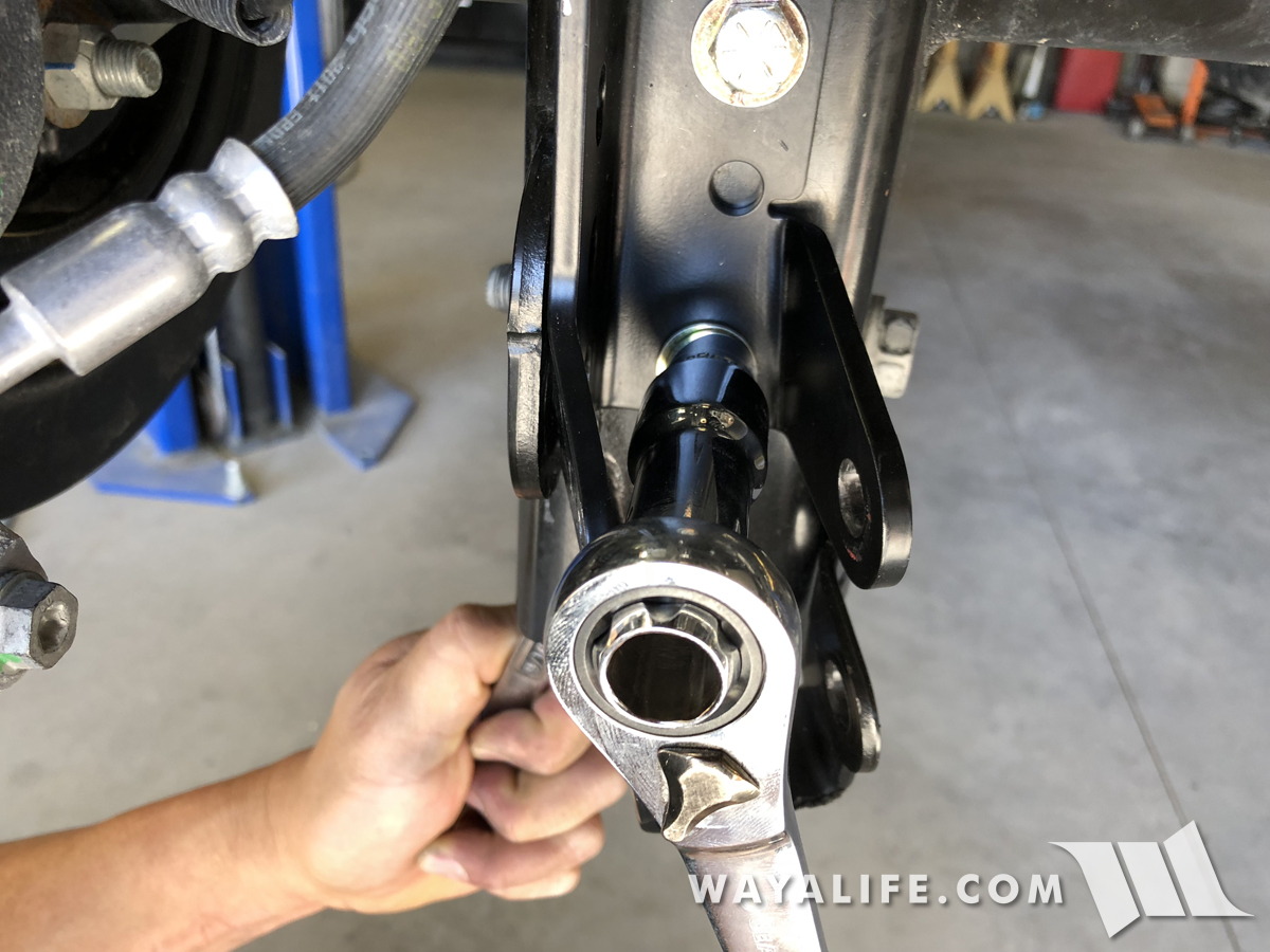
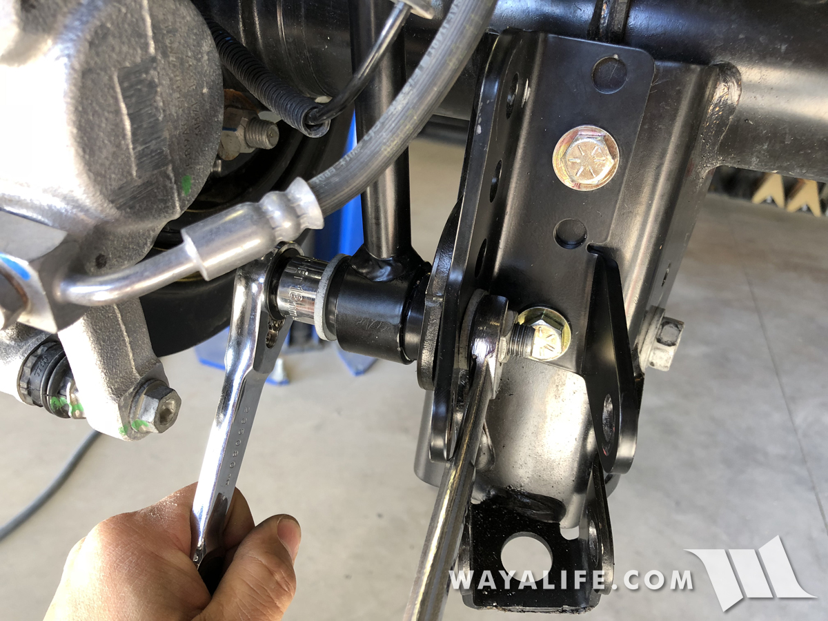
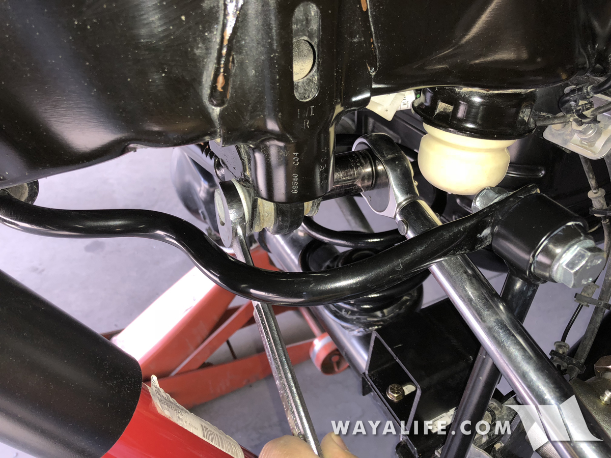
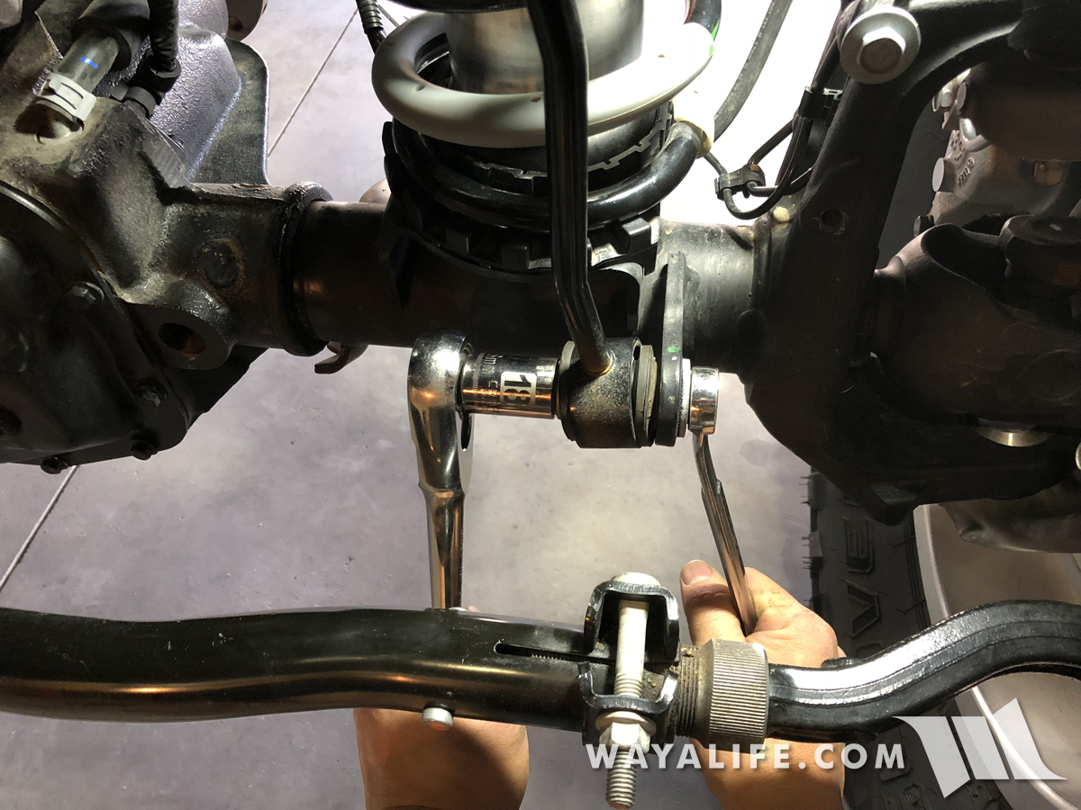
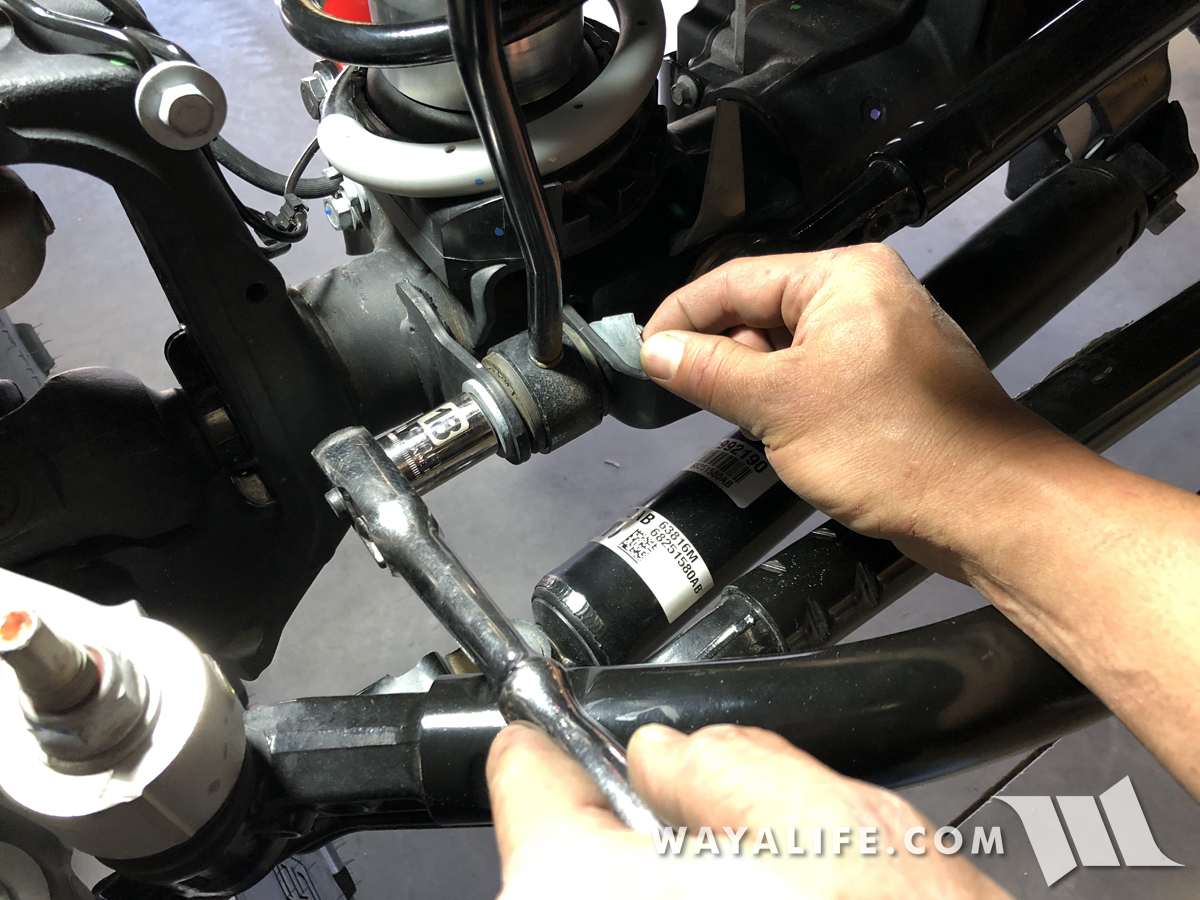
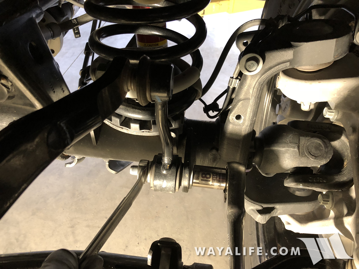
2. Starting from the front of your JL, use an 18mm socket and wrench to remove the bolt and nut securing your driver side front sway bar links to the lower axle mount.
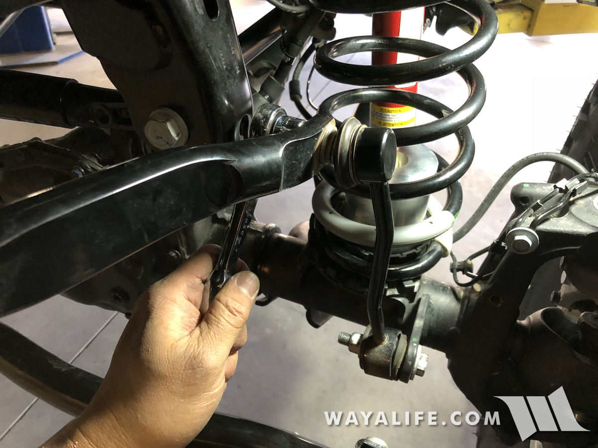
3. The passenger side front sway bar link is tied into the track bar mount and utilizes a flagged nut to help secure it in place. Because of this, you will just need an 18mm socket to remove the bolt.
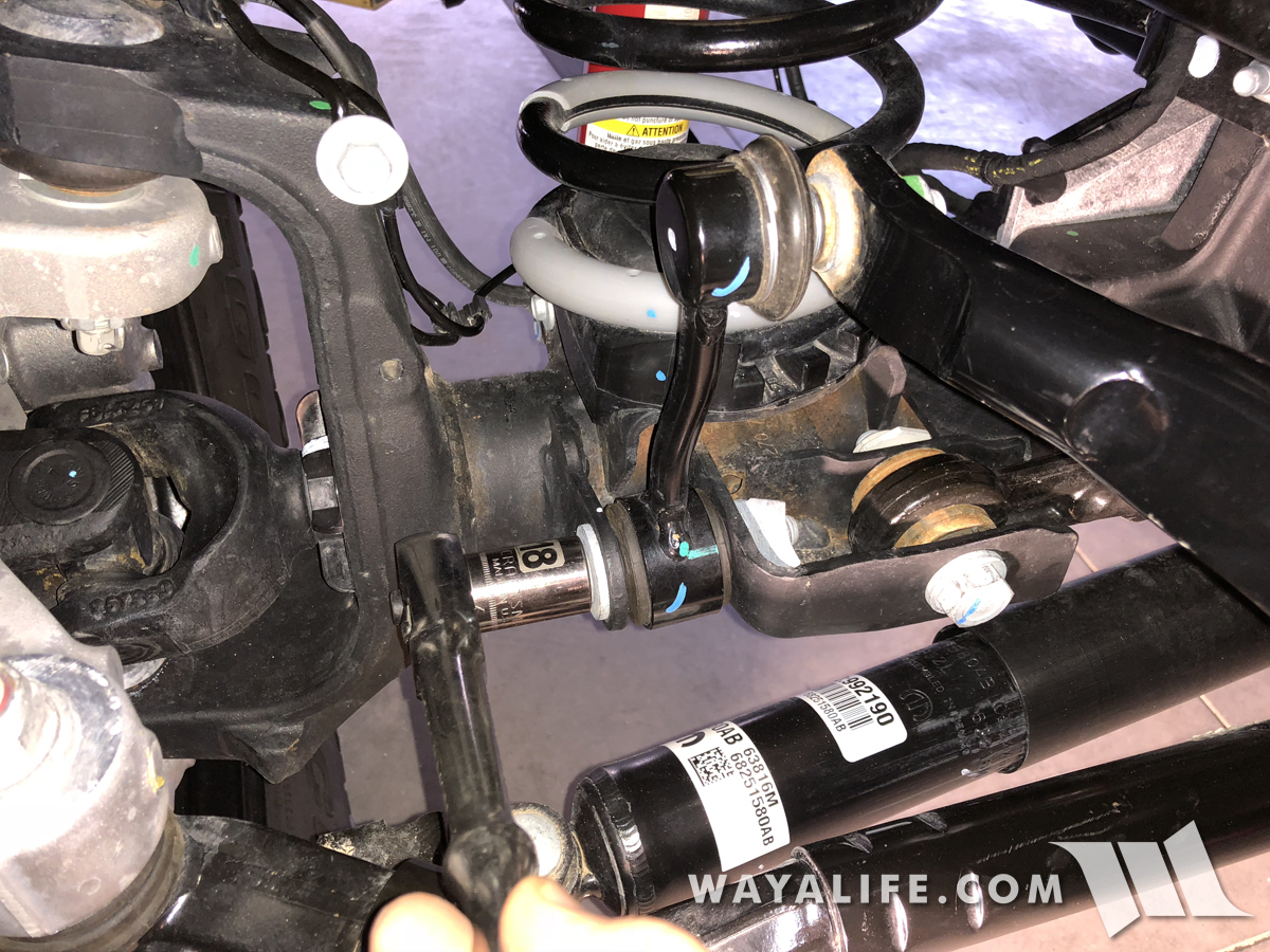
4. Using a 21mm socket, a long ratchet extension and a breaker bar or impact wrench, remove the bolt securing the front track bar bolt to the axle.
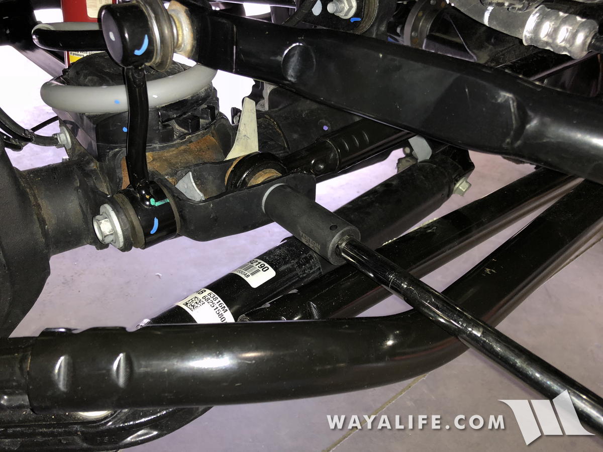
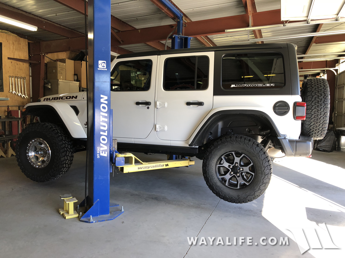
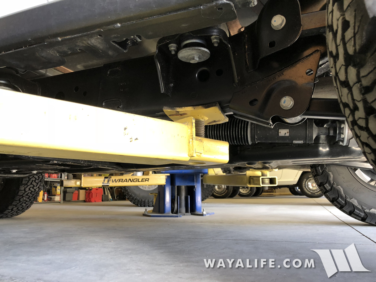
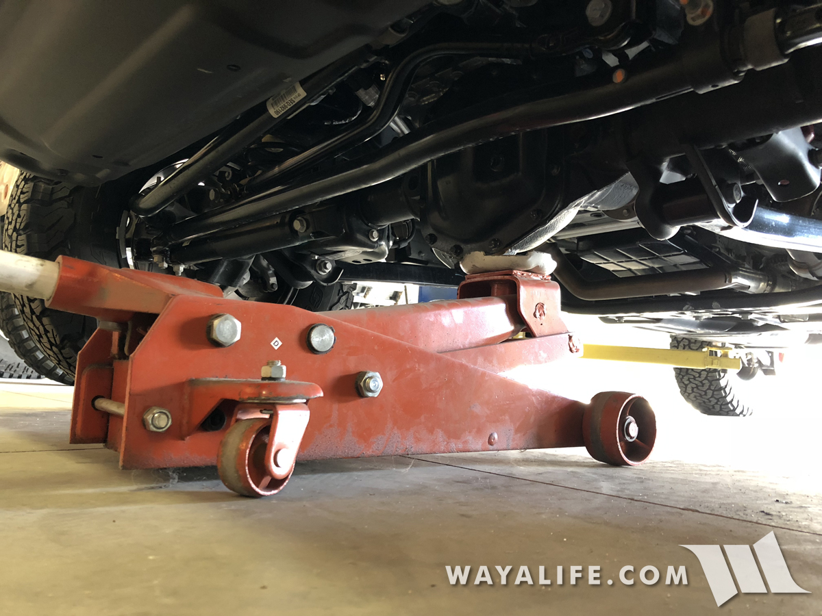
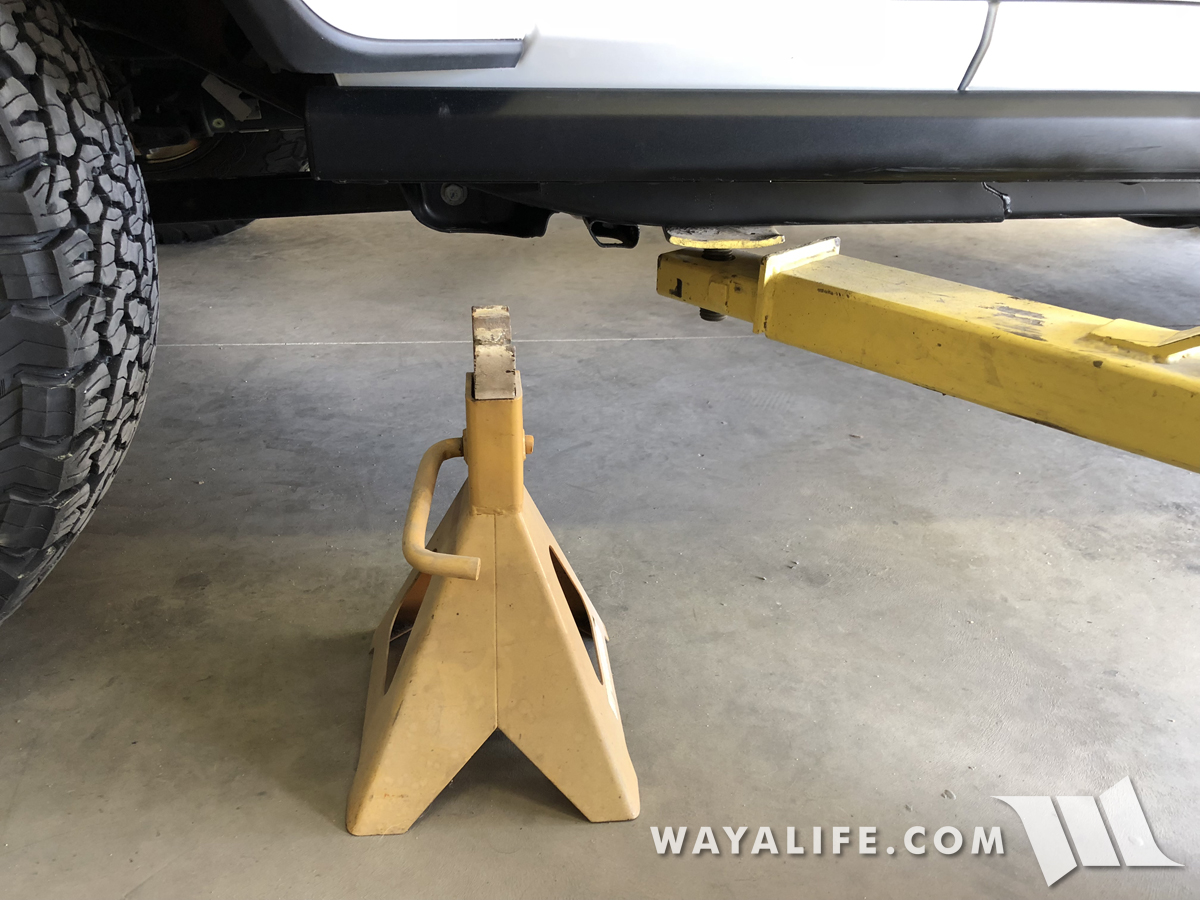
5. Raise the front end of your JL Wrangler from the axle using a floor jack and then set the frame rails onto 2 jack stands, each placed just behind the transmission skid bar. For our purposes, we have a lift and are racking up our JL Wrangler but as you can see, the arms are still positioned in the same location.
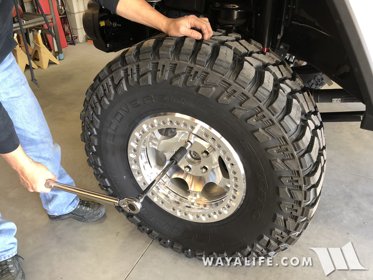
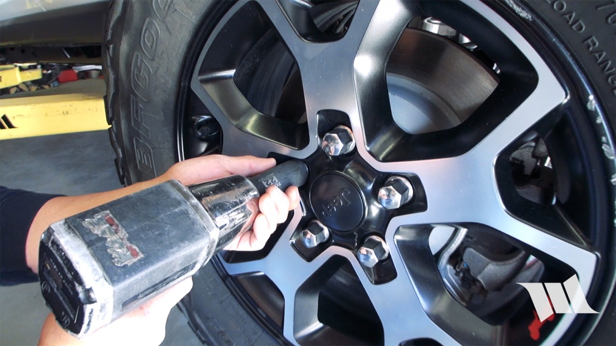
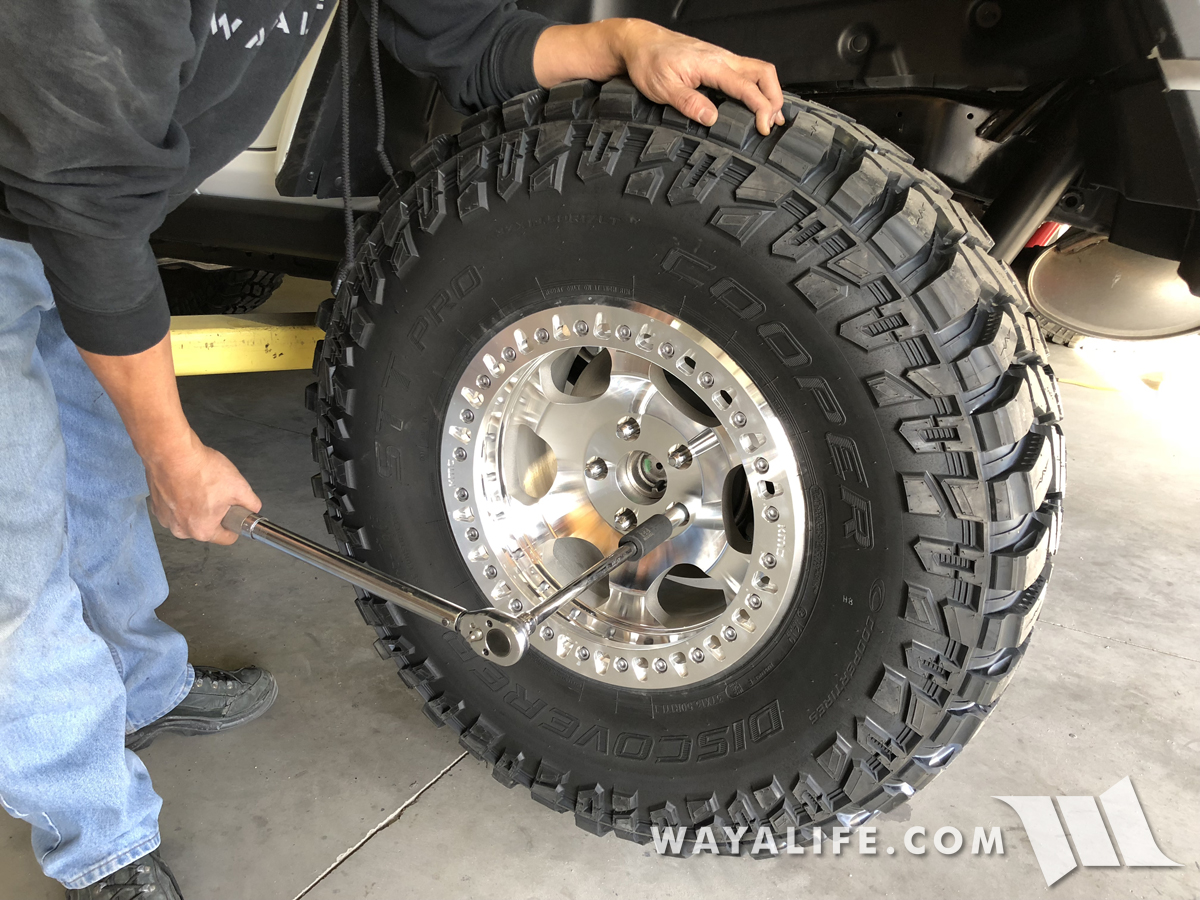
6. Use a 22mm socket to remove the lug nuts securing your front wheels to the axle and then set them aside.
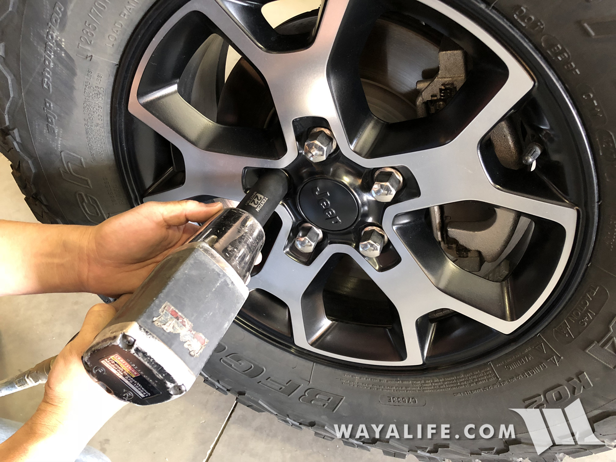
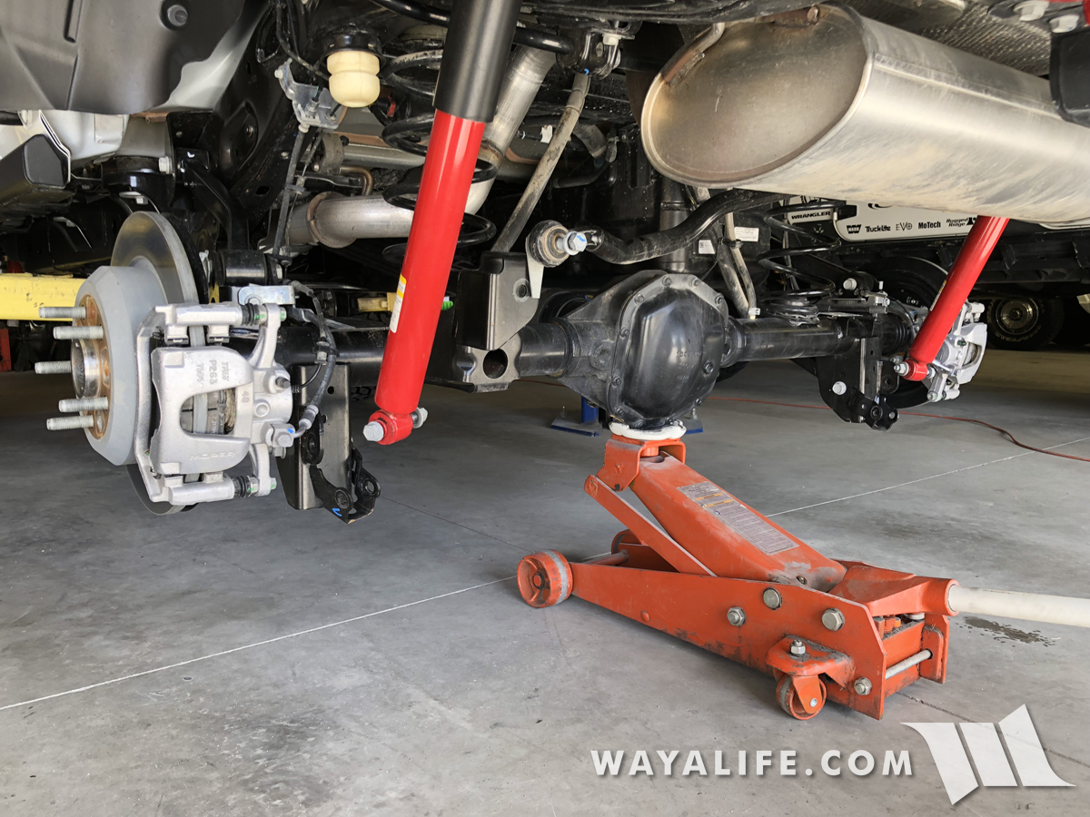
7. Use your floor jack to carefully lift the front axle just enough to help support the weight of it. You do NOT want to raise it to the point where your frame rails lift off the jack stands.
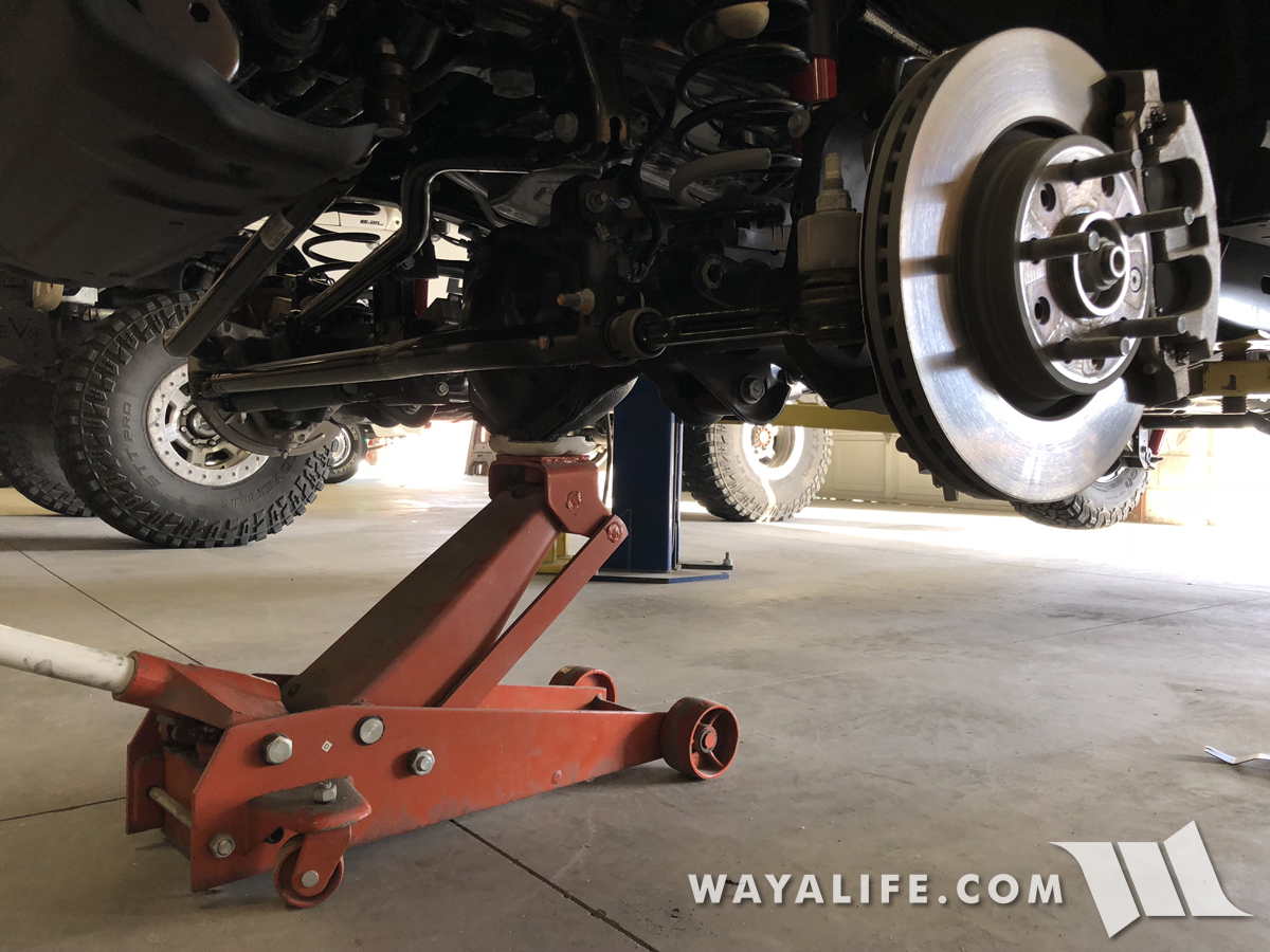
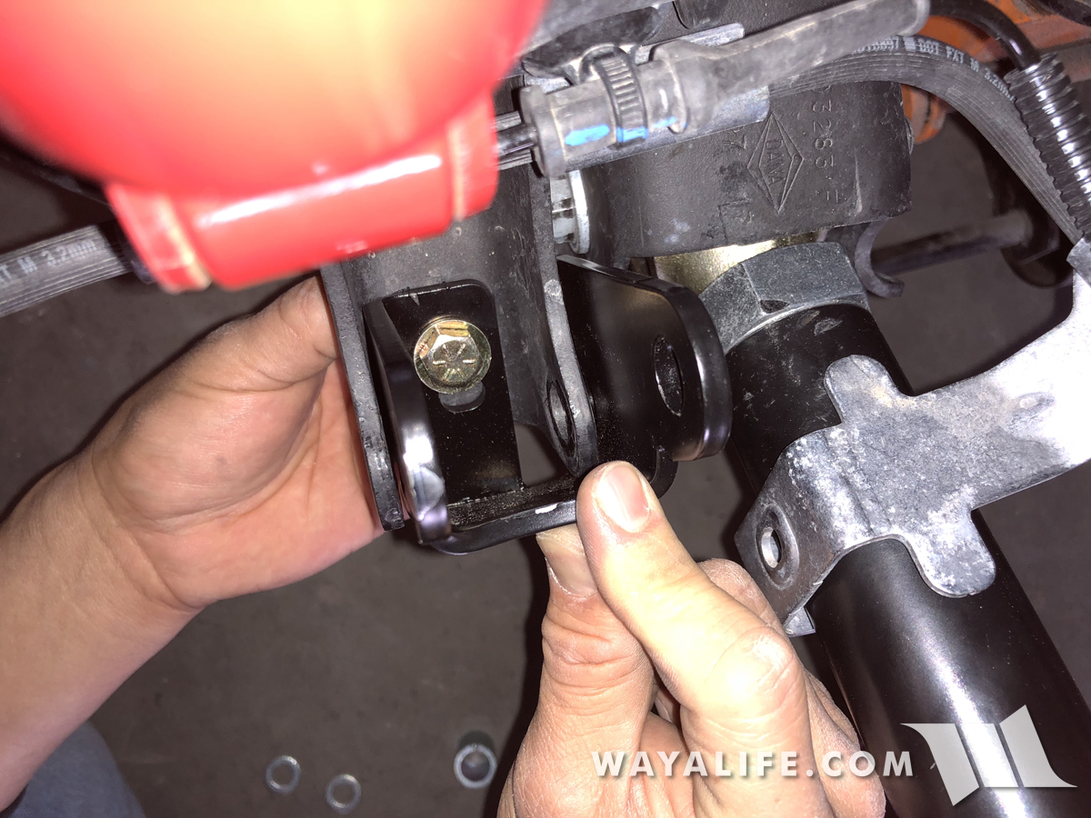
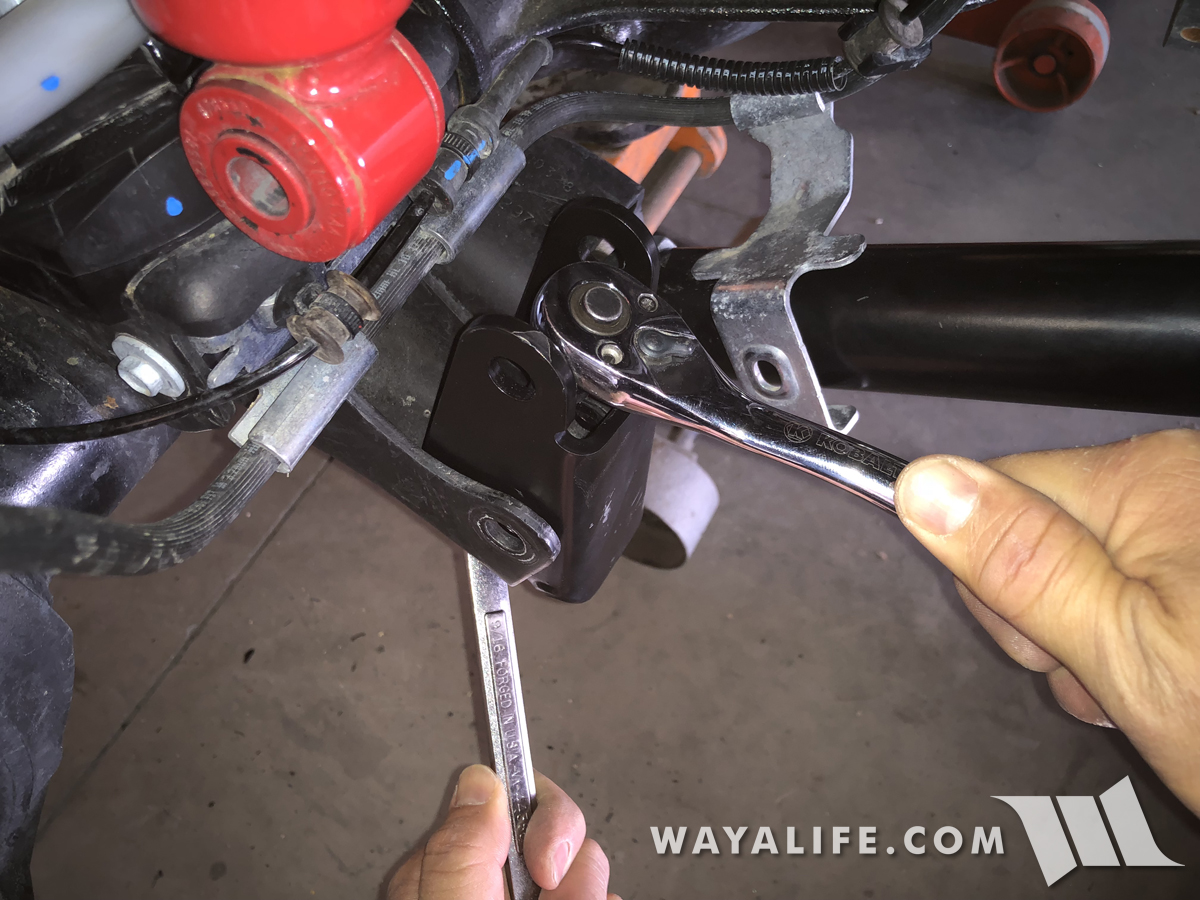
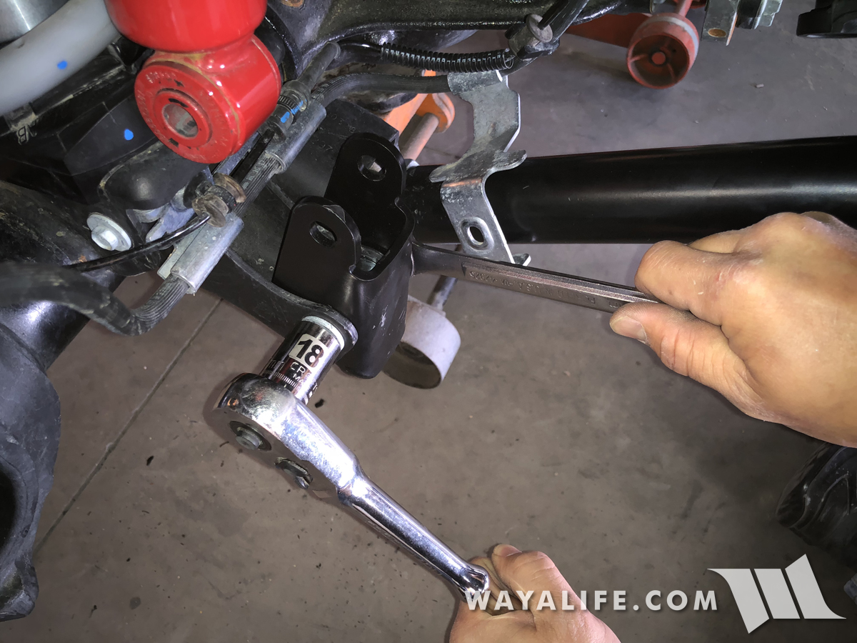
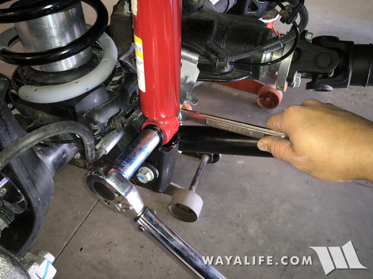
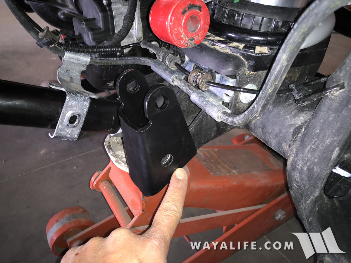
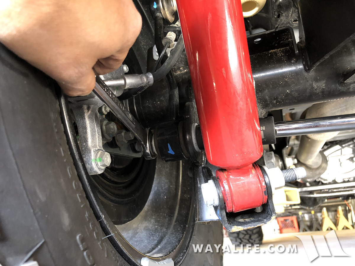
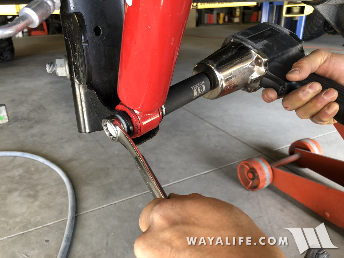
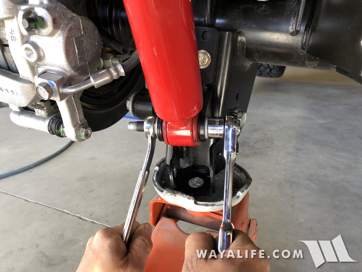
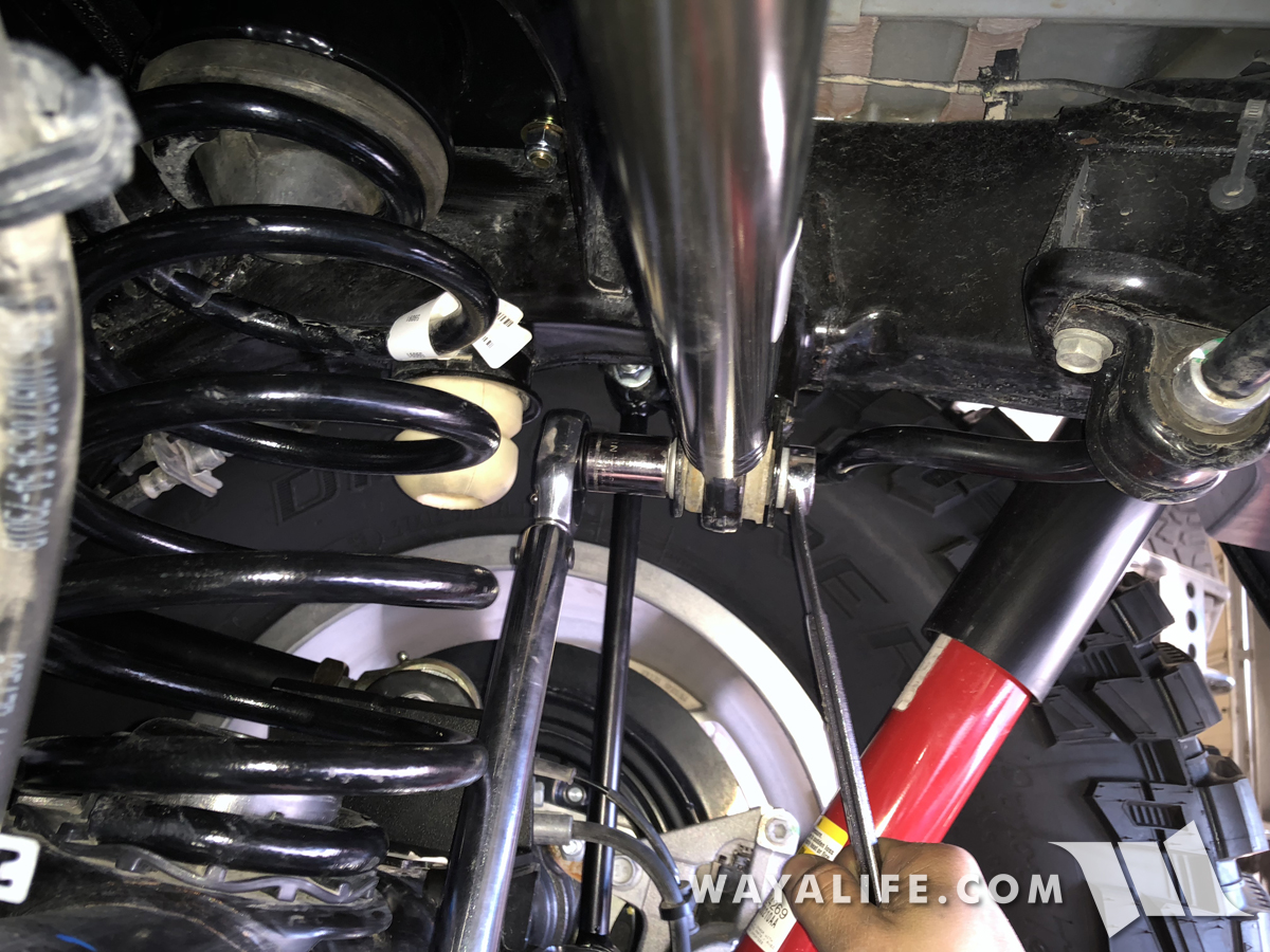
8. Using an 18mm socket and wrench, remove the bolts and nuts securing your shocks to the axle mounts.
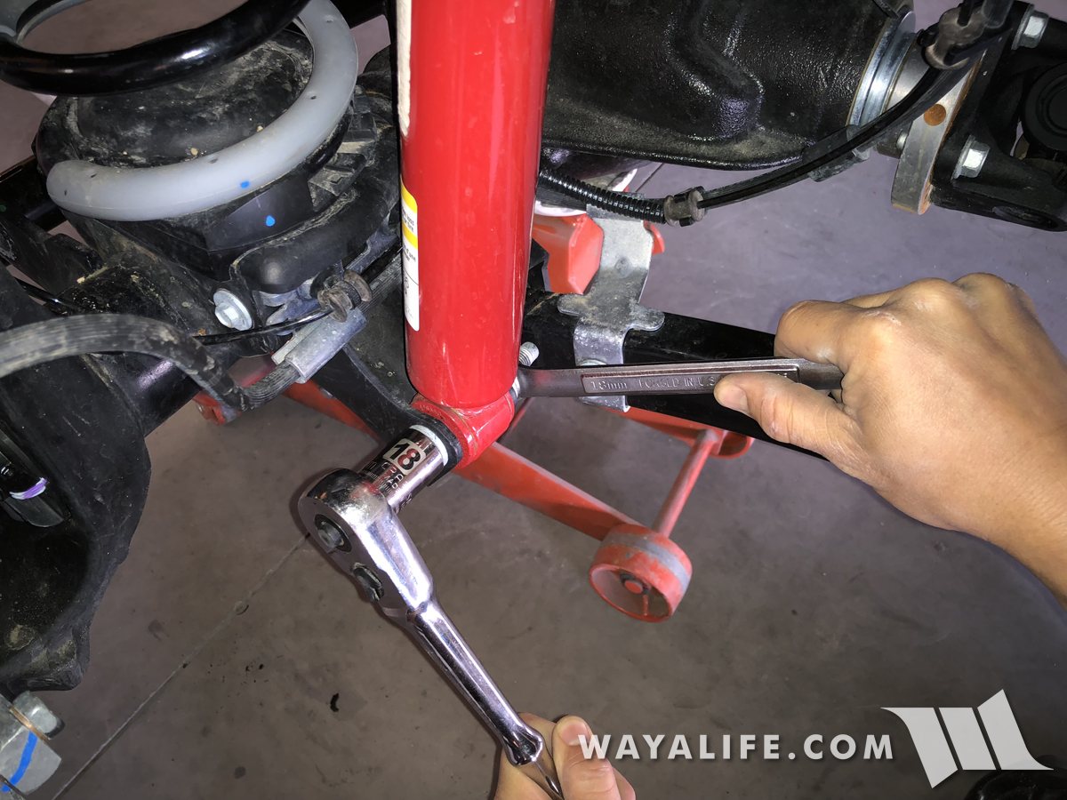
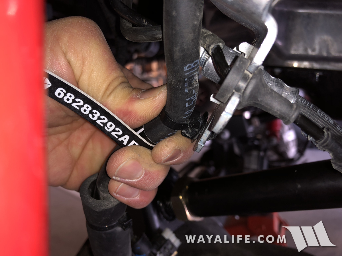
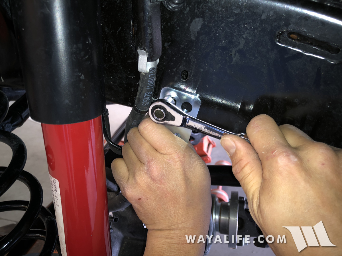
9. Use a 10mm socket to remove the bolt securing the brake hard lines to the frame rail.
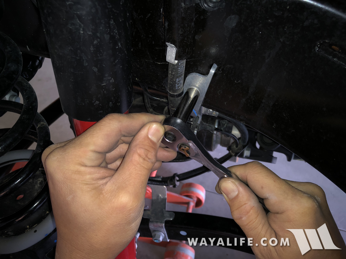
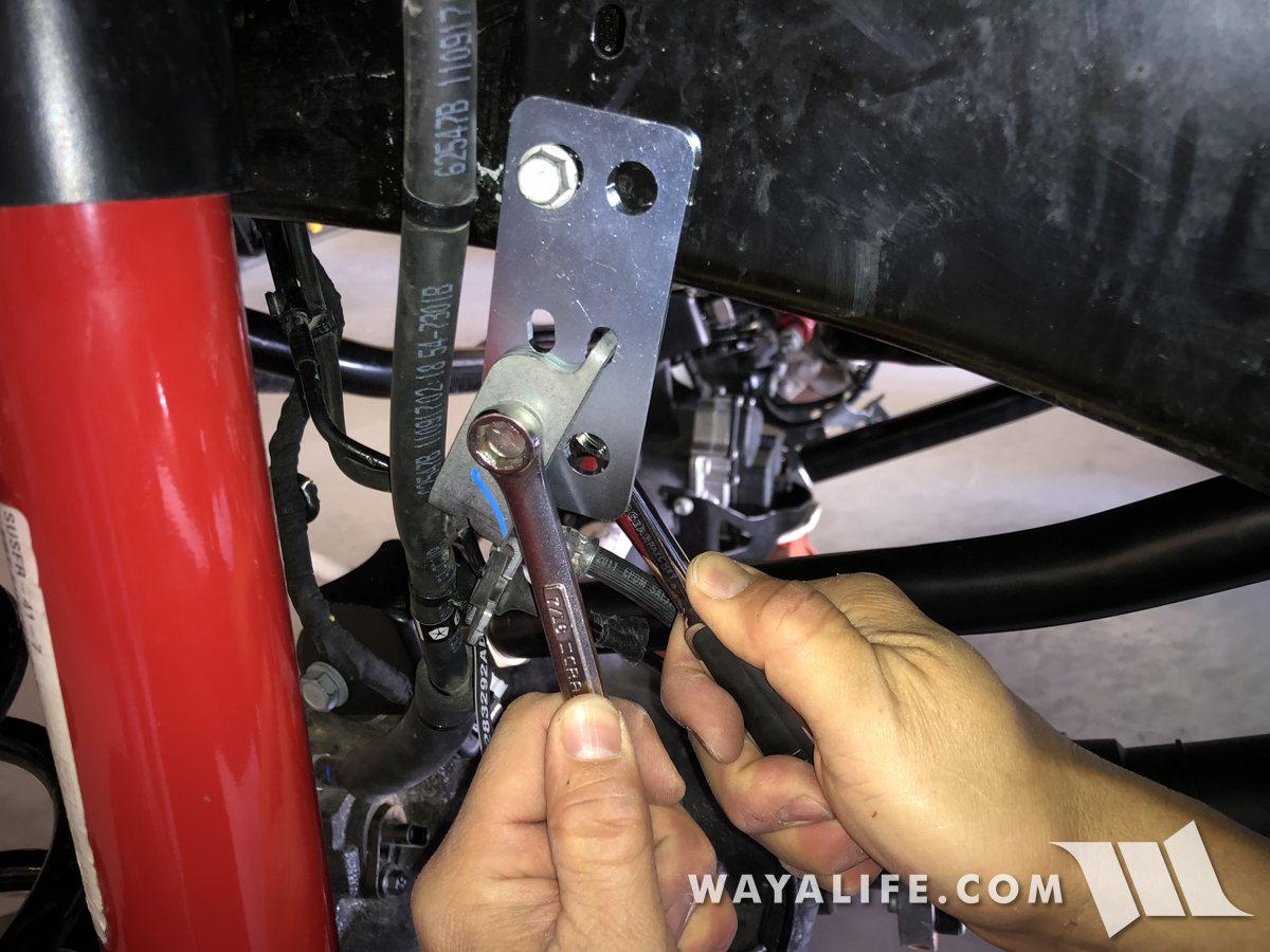
10. Use a 15mm socket to remove the nut securing the brake hose and speed sensor wiring to the lower control arms.
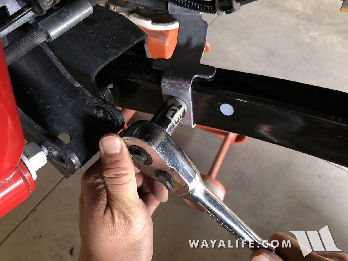
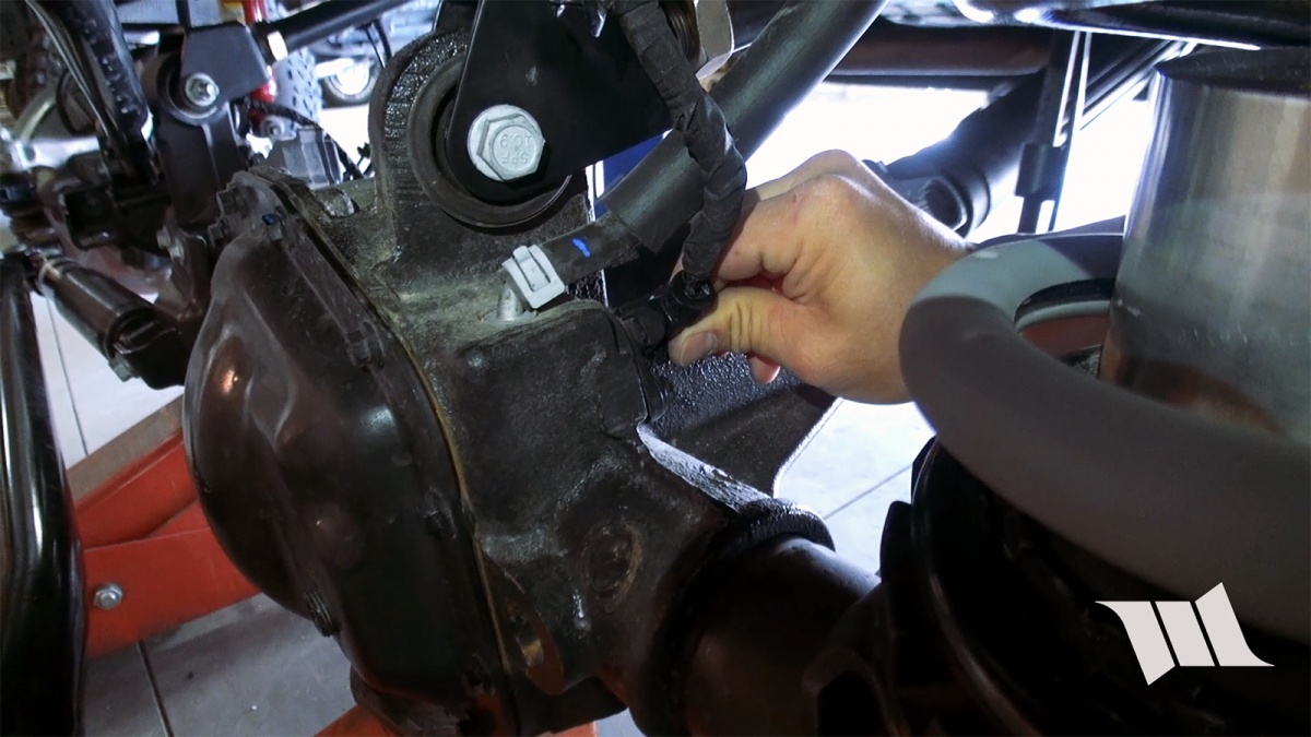
11. Use a trim pry tool to separate the push tab securing the locker wiring harness to the driver side upper control arm fork.
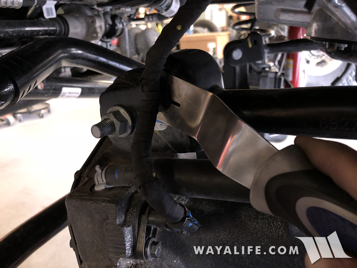
12. Again, use your trim pry tool to separate the push tab securing the locker wiring harness to the inside of the frame rail.
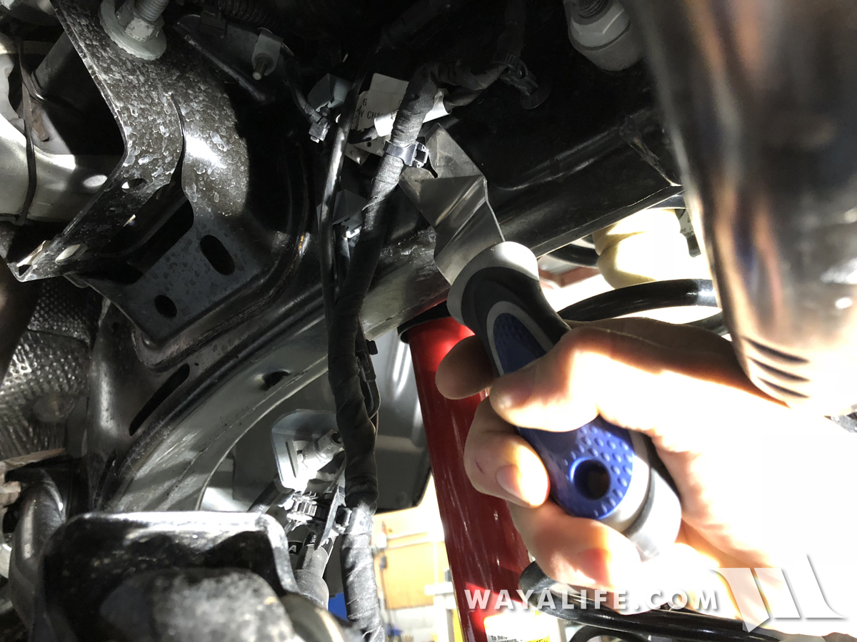
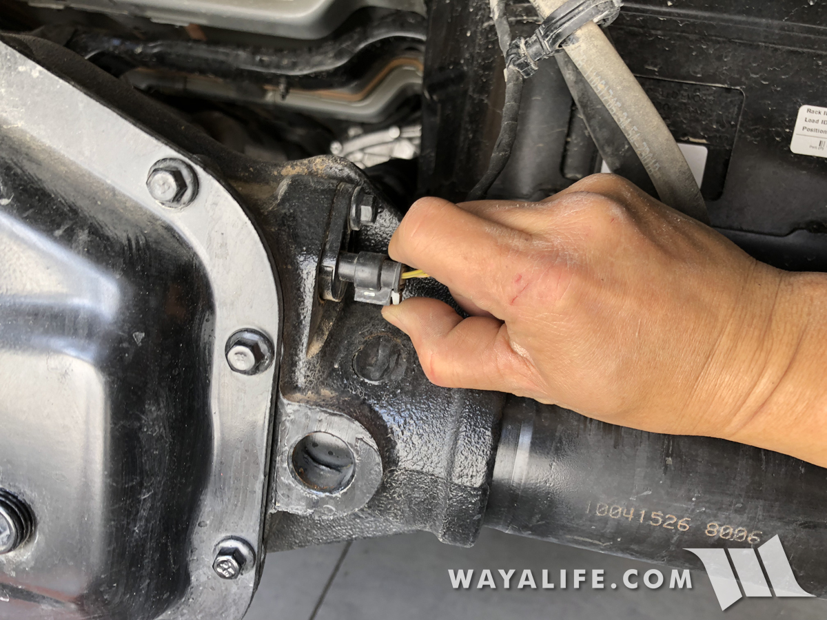
13. Unplug the front locker wiring harness by squeezing the gray locking tab and pulling straight back.
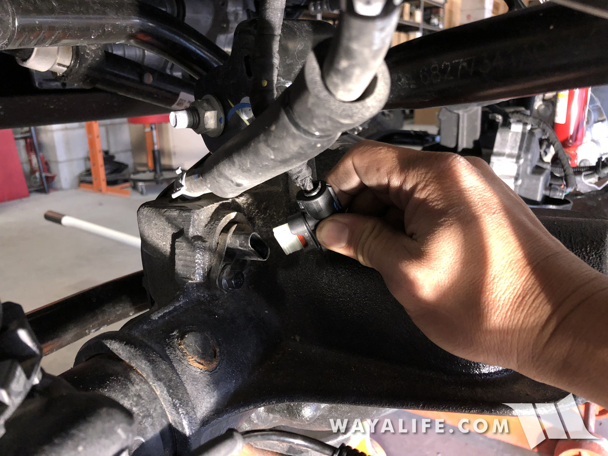
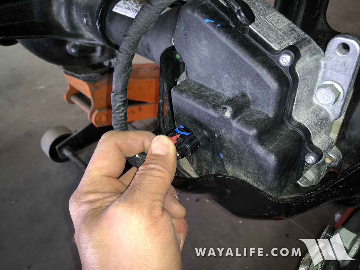
14. Moving over the passenger side, use a trim pry tool to separate the push tab securing the FAD wiring harness to the passenger side upper control arm fork.
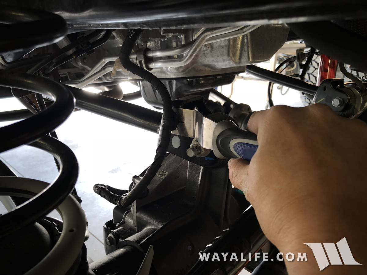
15. Again, use your trim pry tool to separate the push tab securing the FAD wiring harness to the inside of the frame rail.
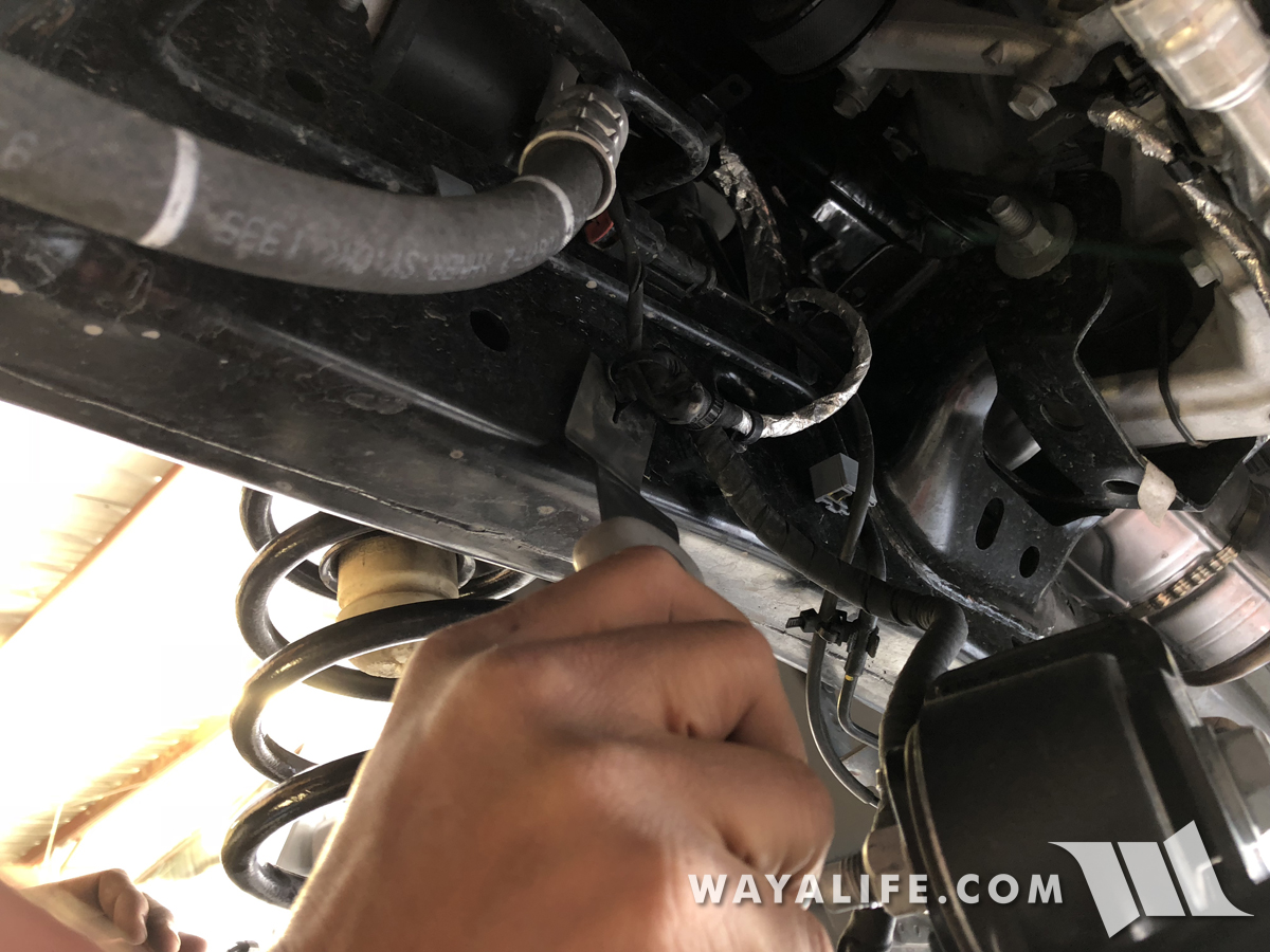
16. Unplug the FAD wiring harness by squeezing the red locking tab and pulling straight back.
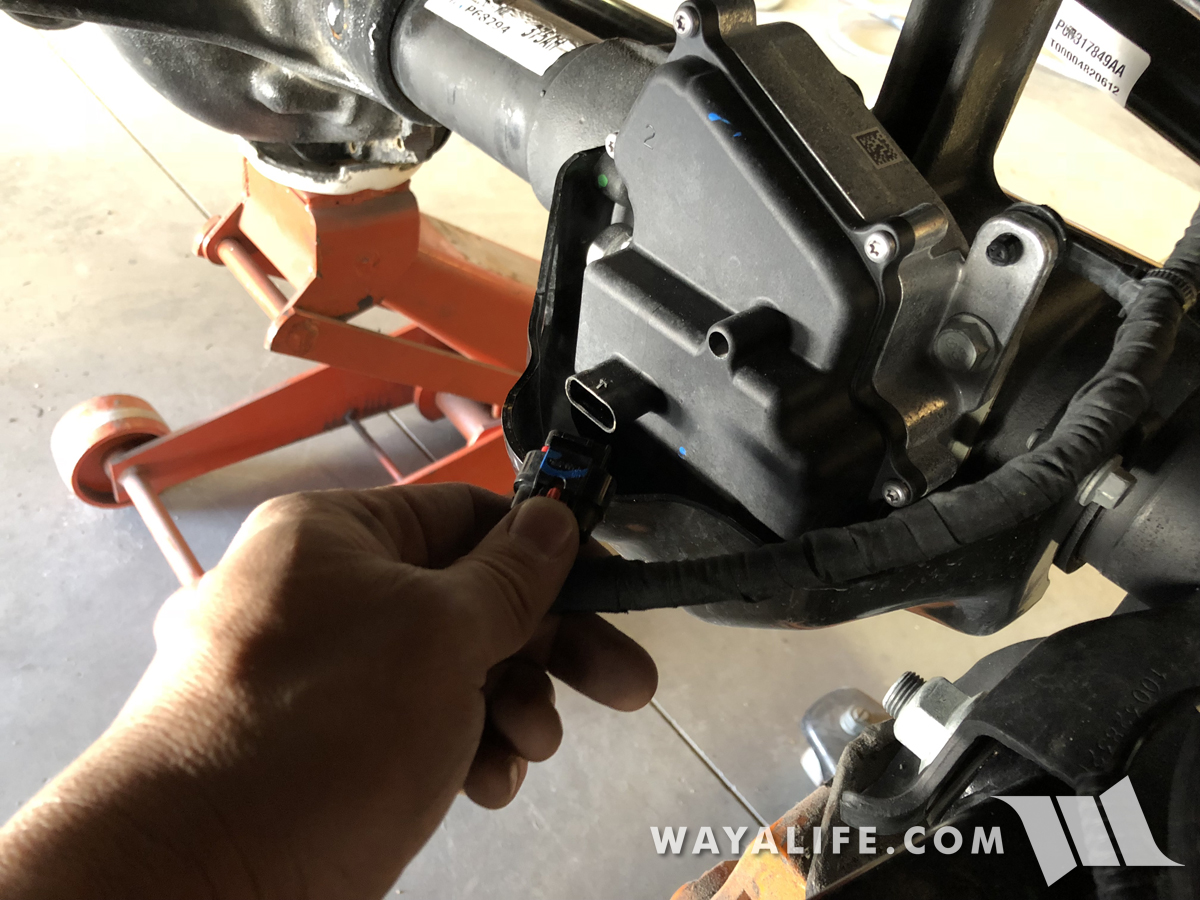
17. Use your trim pry tool once again to separate the push tab securing the FAD wiring harness to the back of the unit.
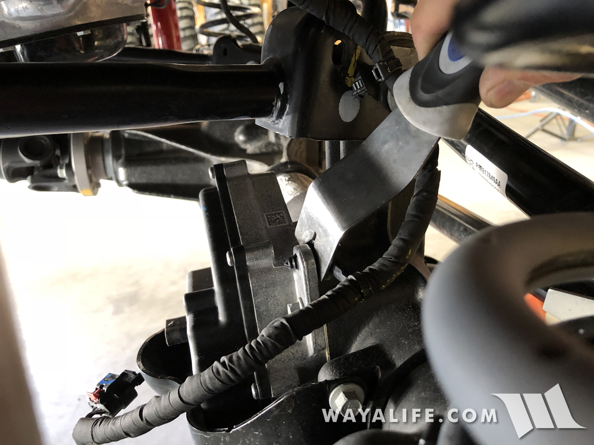
18. Using your floor jack, slowly lower your front axle making sure that there aren't any wires or components getting hung up. Continue to lower your axle to the point that you can simply slip your coils out from their perches.
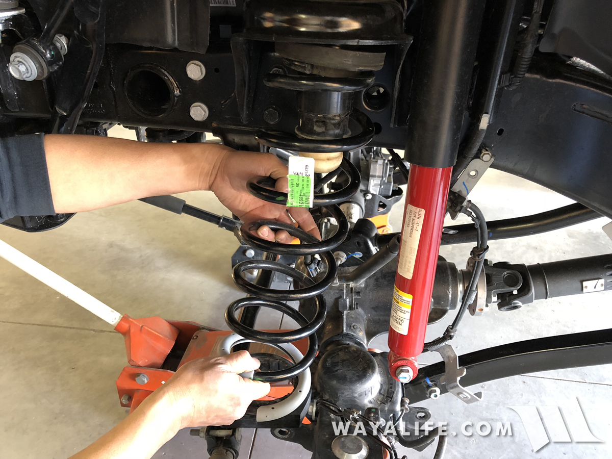
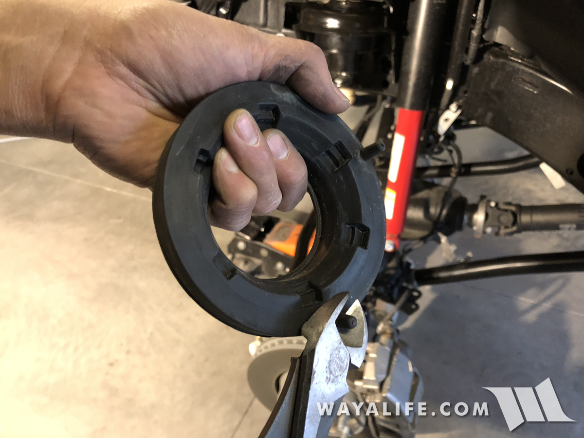
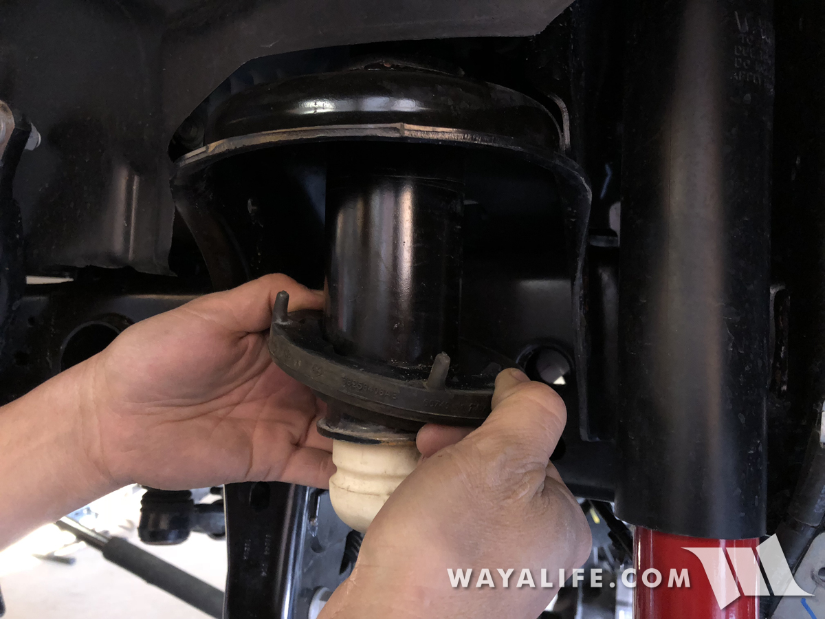
19. Remove the upper spring perch rubber isolators by slipping it down and off the bump stop towers. Set them aside for now as they will be reused.
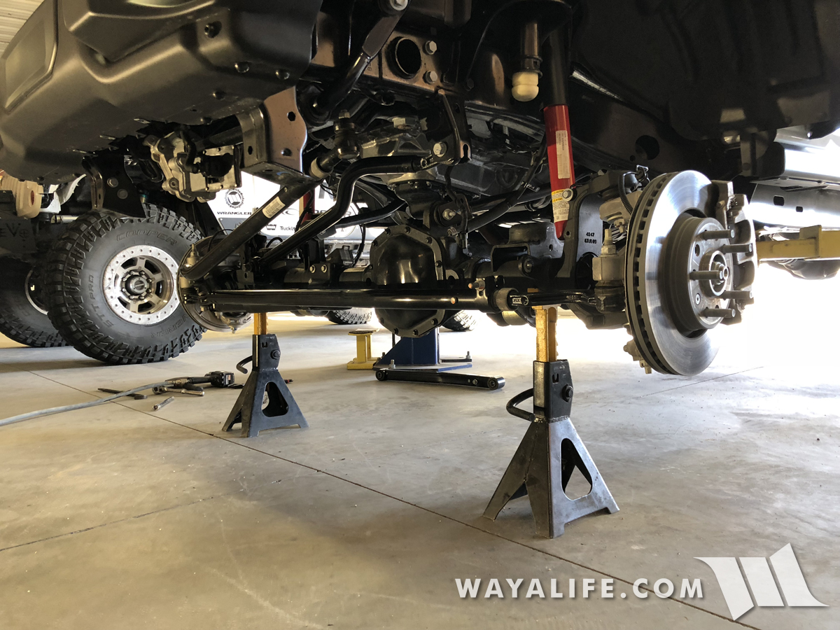
20. If you are installing new heavy duty adjustable control arms, it'll be helpful to support the weight of your front axle with a couple of floor jacks or jack stands as shown here. I should note that this is not required but it will make things easier to work on.
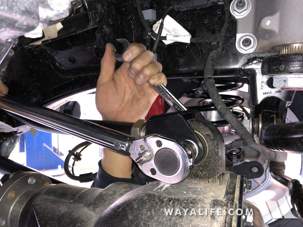
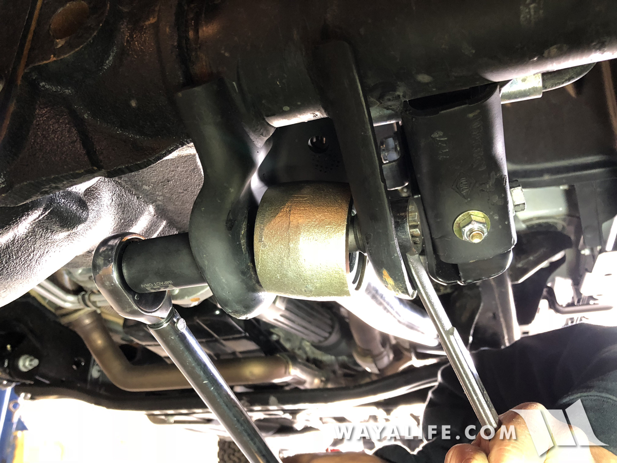
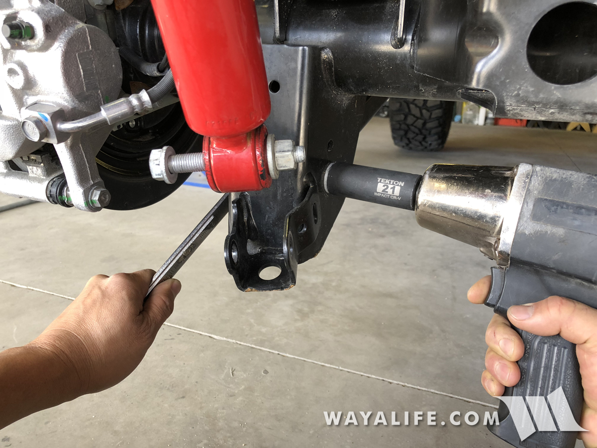
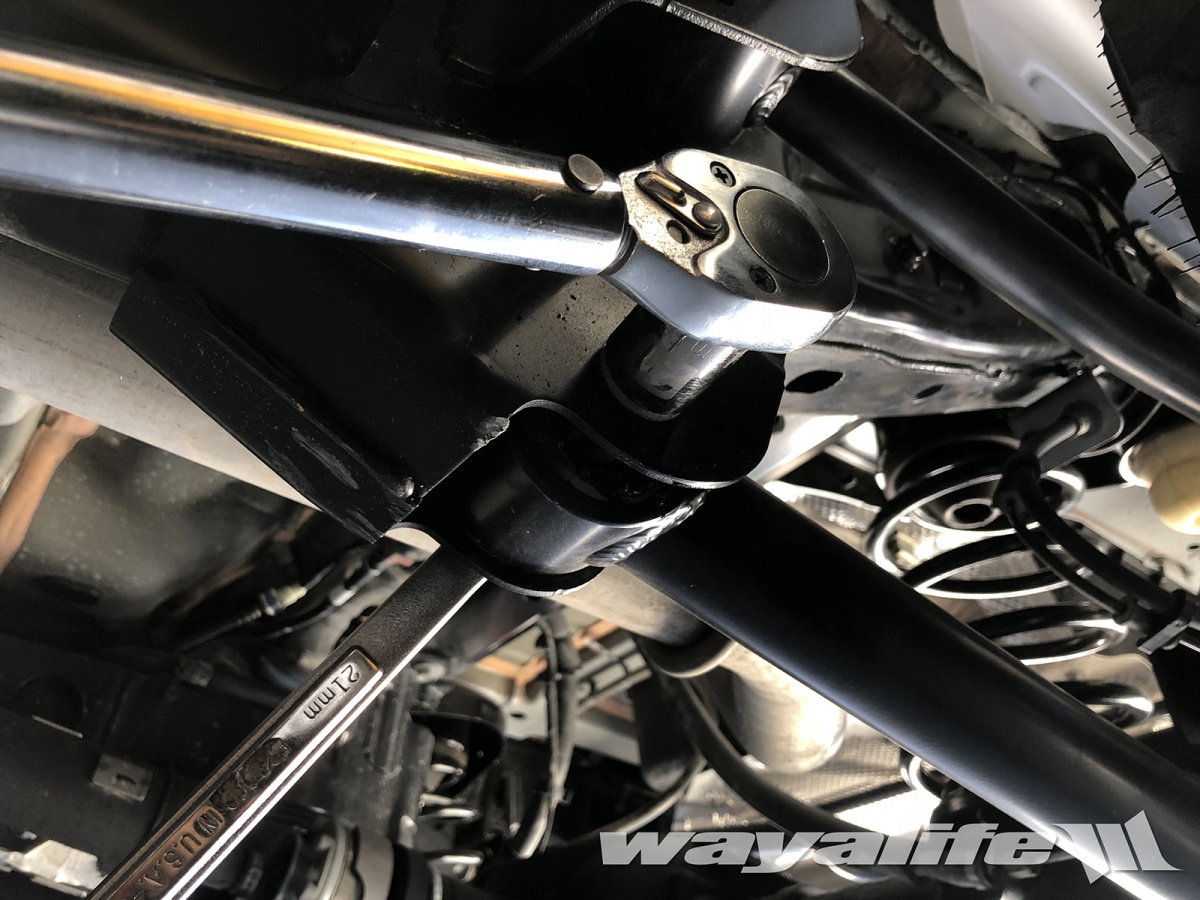
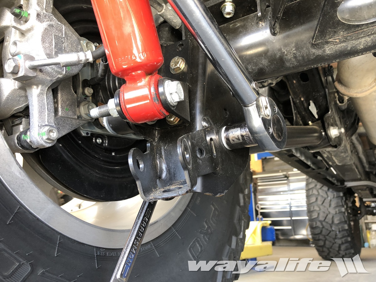
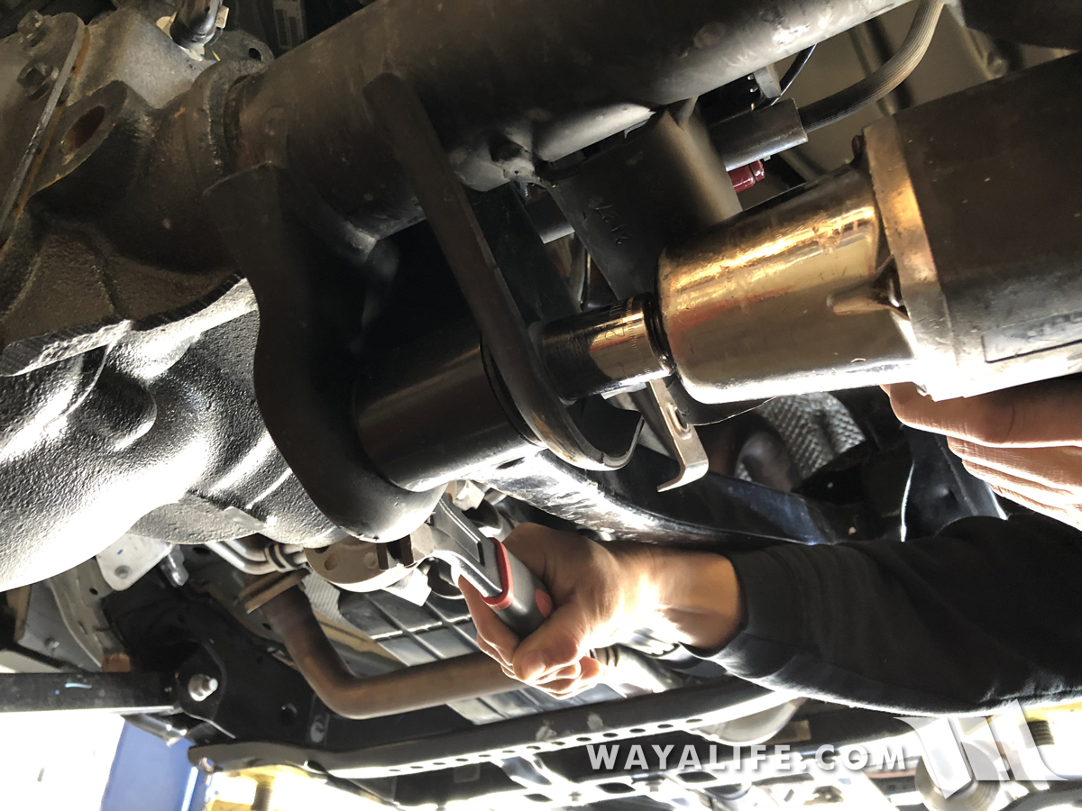
21. Remove the bolt and nut securing the driver side front lower arm to the axle mount using a 21mm socket and 24mm wrench or large crescent wrench. An impact wrench or breaker bar will be required for this job.
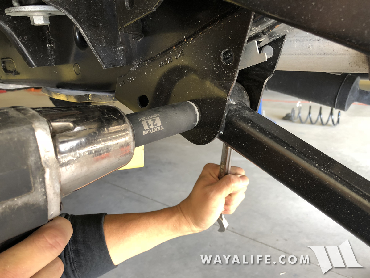
22. Again, use a 21mm socket and 24mm wrench or large crescent wrench to remove the bolt and nut securing the driver side front lower arm to the frame mount . An impact wrench or breaker bar will be required for this job.
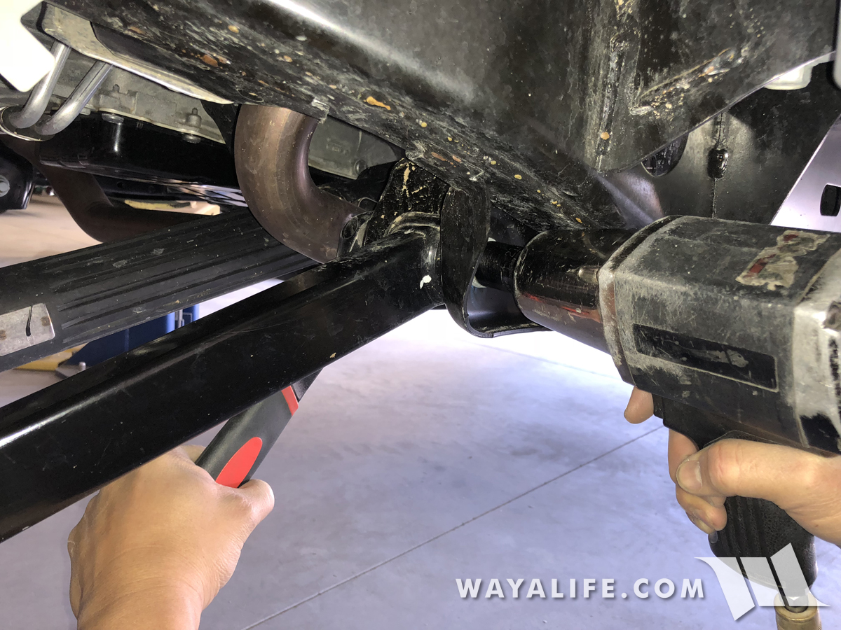
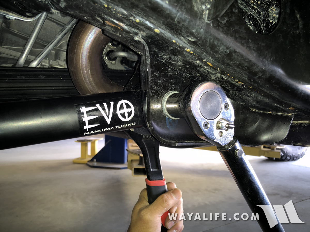
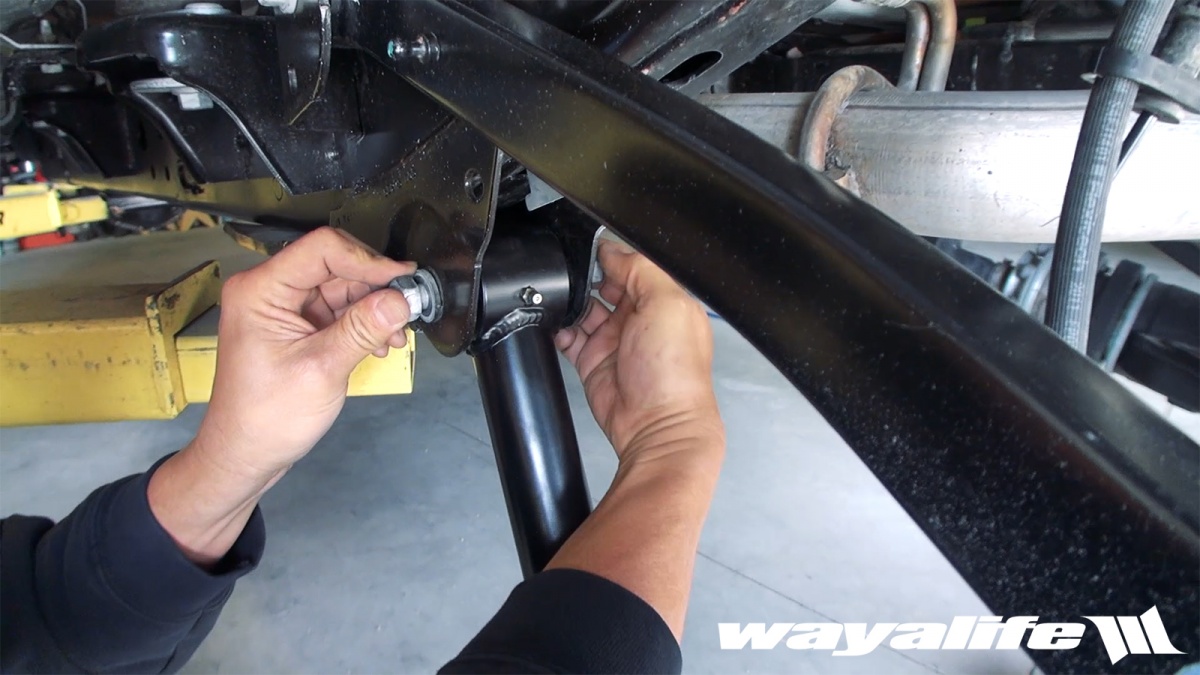
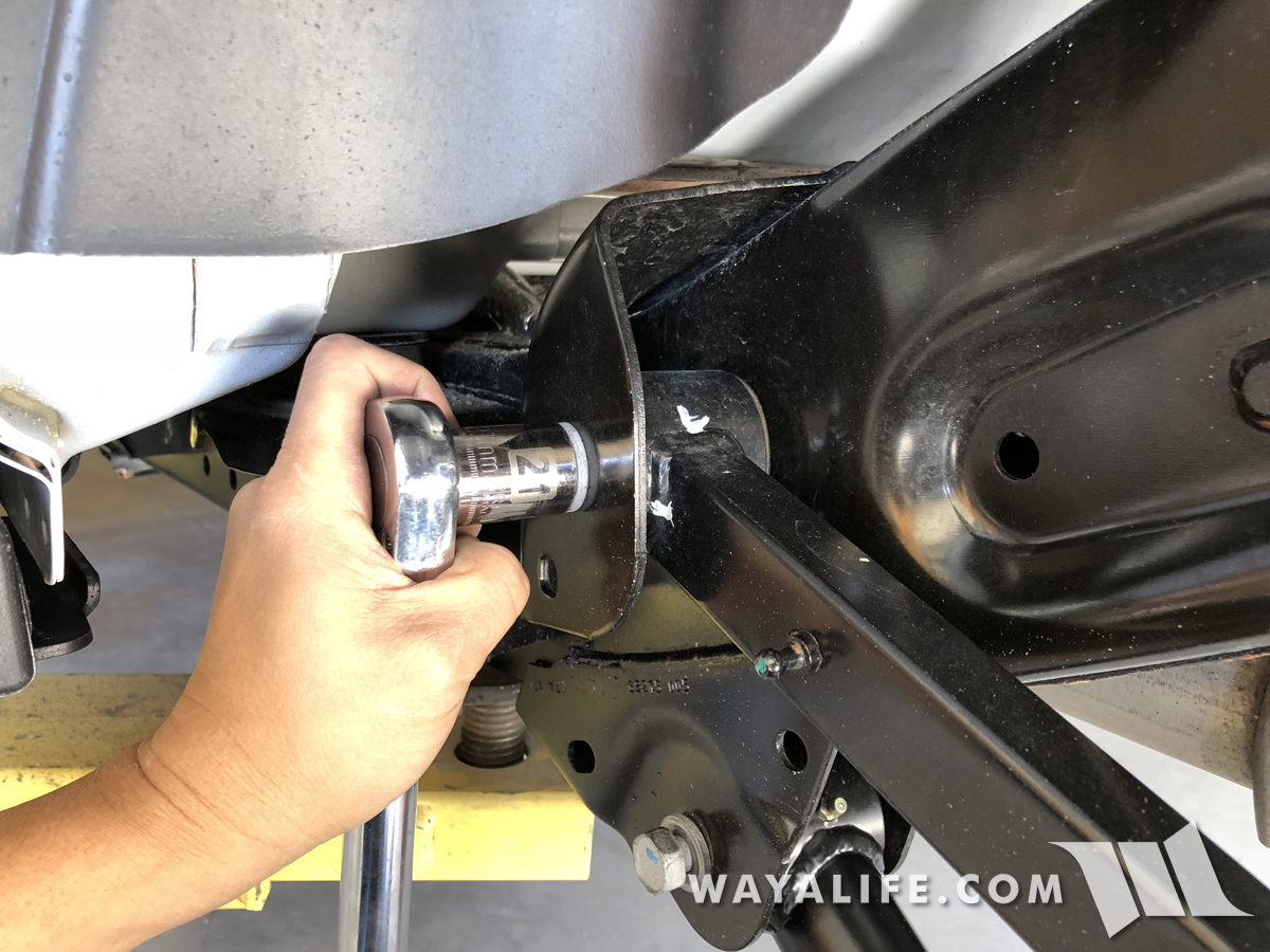
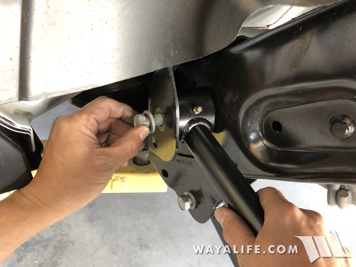
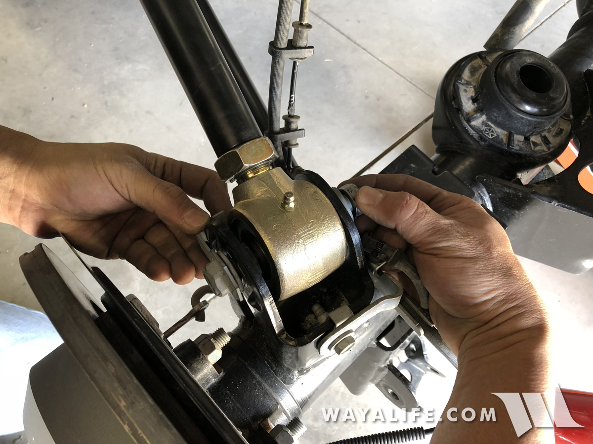
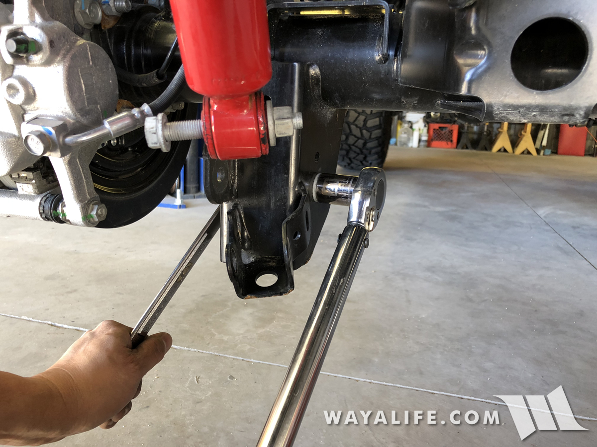
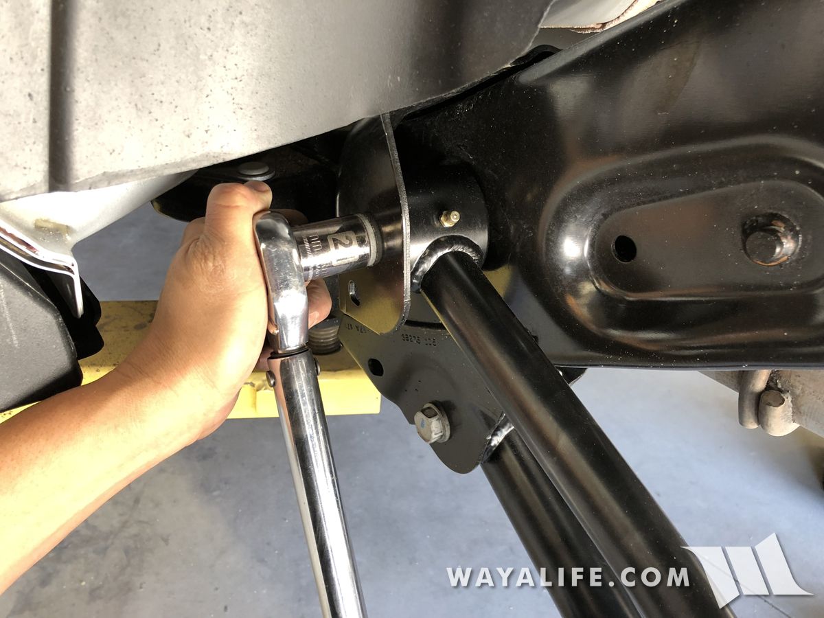
23. Making sure that the zerk nipples are pointing upward, install your new EVO front lower control arm onto the frame mount using the factory bolt and nut. I should note that the 16mm bolt will make for a tight fit and you'll need to encourage it through by giving it a few taps with a hammer.
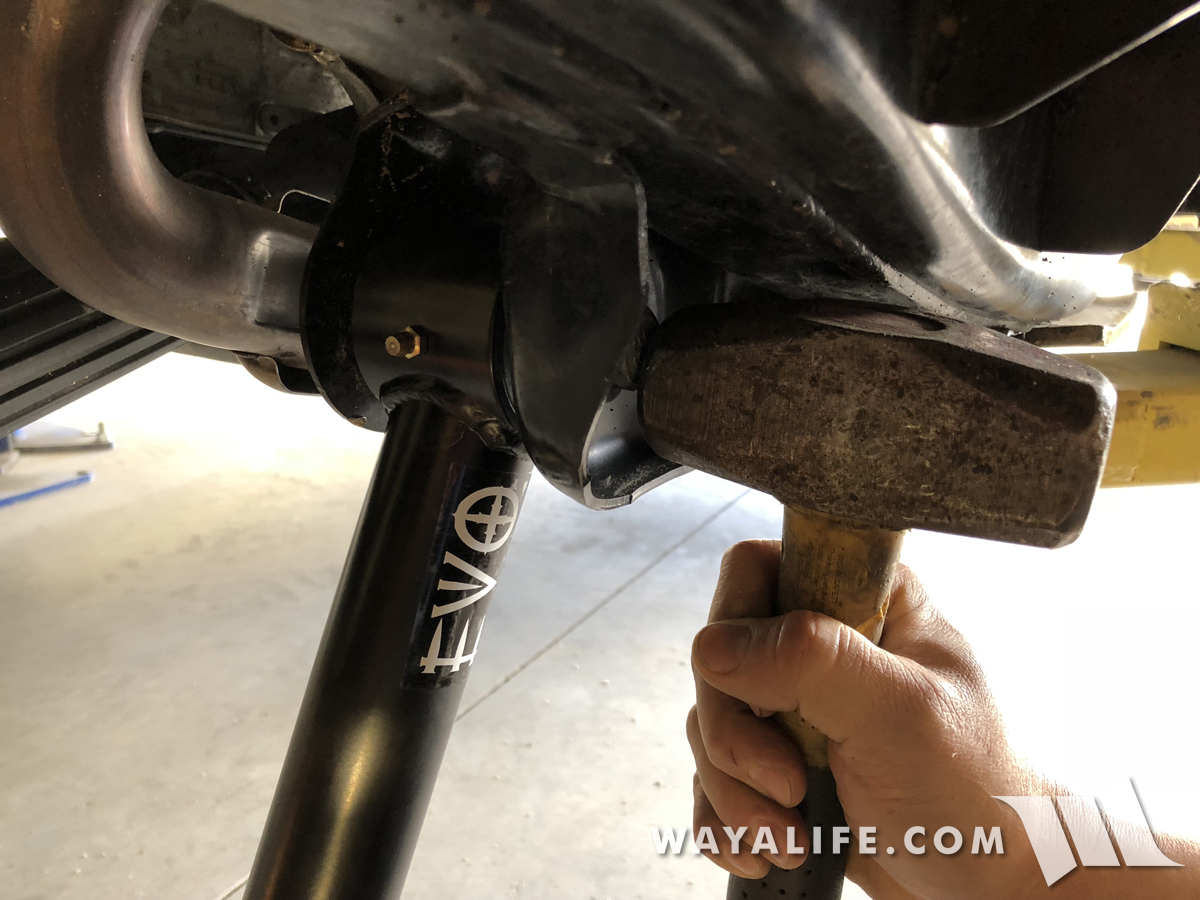
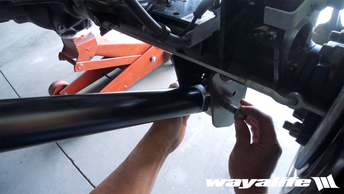
24. You will now want to install the EVO front lower control arm onto the axle mount using the factory bolt and nut. Again, it'll be a tight fit and a few taps with a hammer will be needed to help it through.
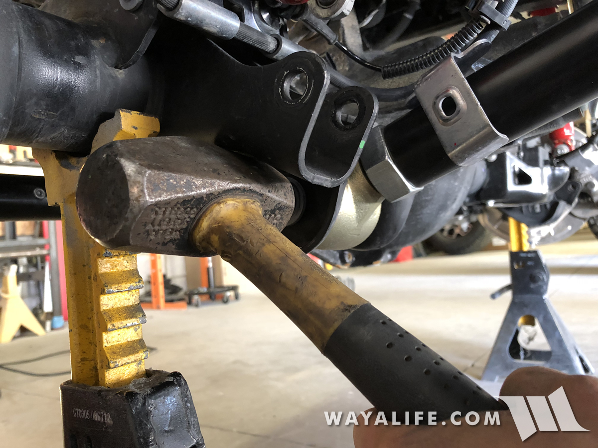
25. Being that the EVO control arms use Johnny Joints, you can now tighten the bolts to 103 ft. lbs. of torque + an additional 50° but I would still recommend that you do a final torque check once the full weight of your JL is on the ground.
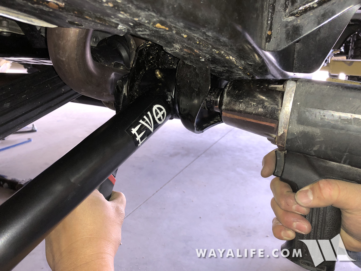
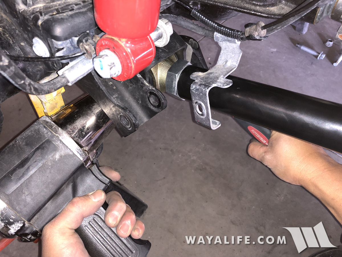
26. Repeat Steps #21-25 on the passenger side of your JL.
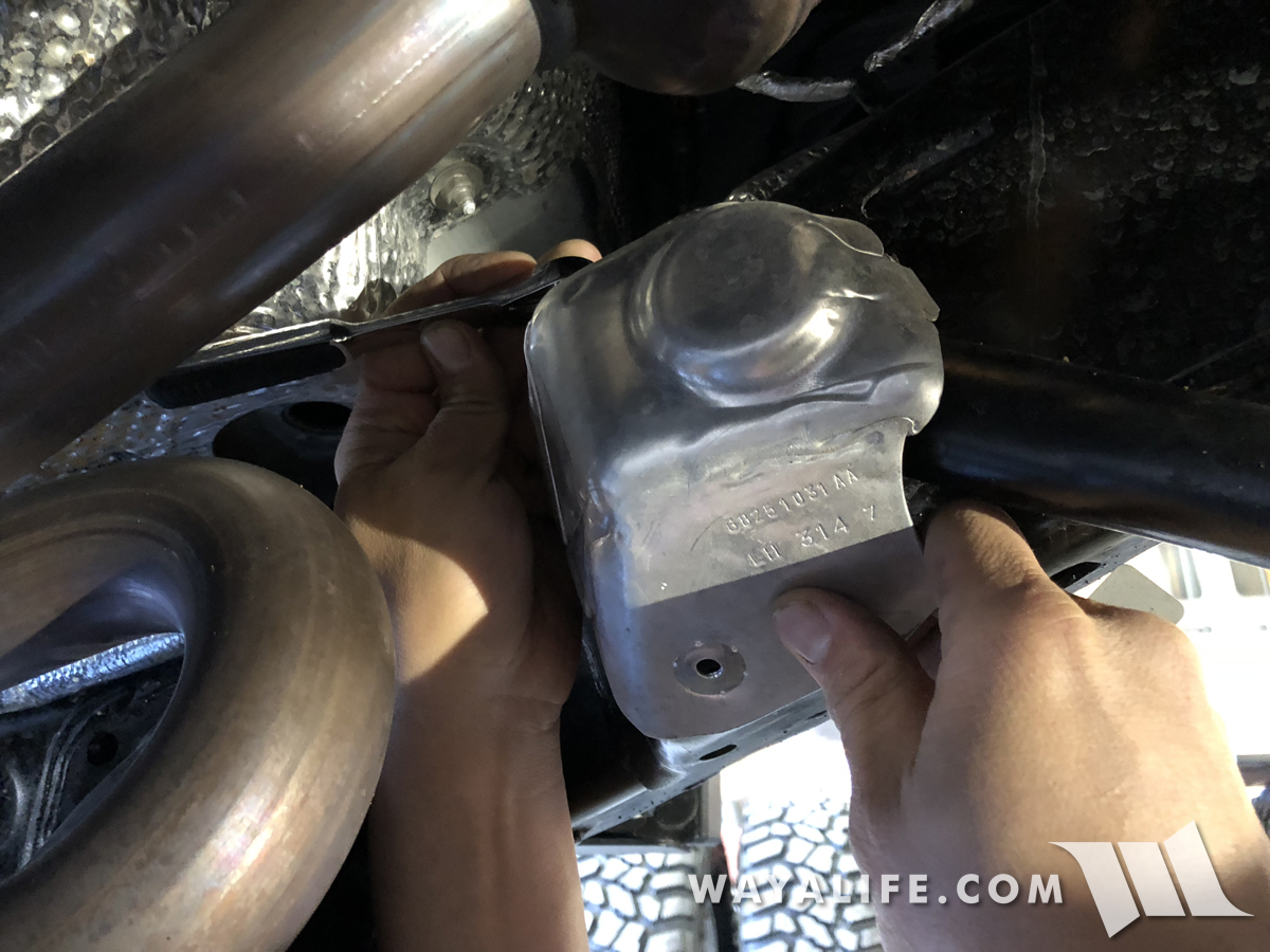
27. Moving over to the front upper control arms, use a 10mm socket to remove the 2 bolts securing the heat shields to the frame mount.
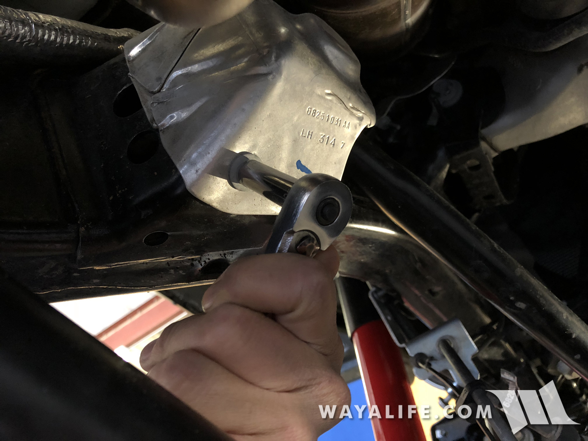
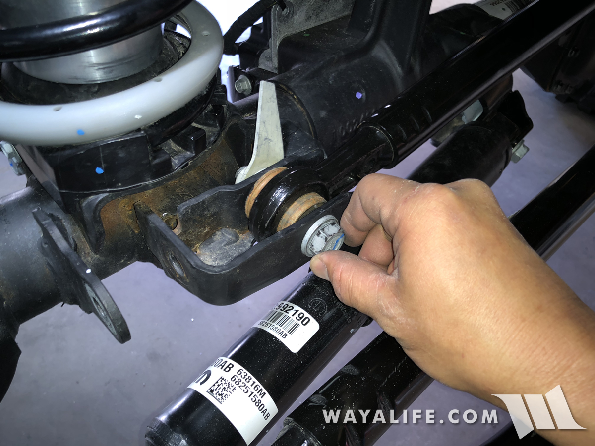
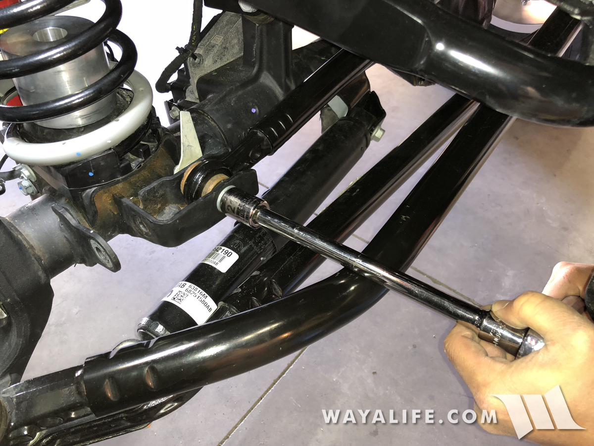
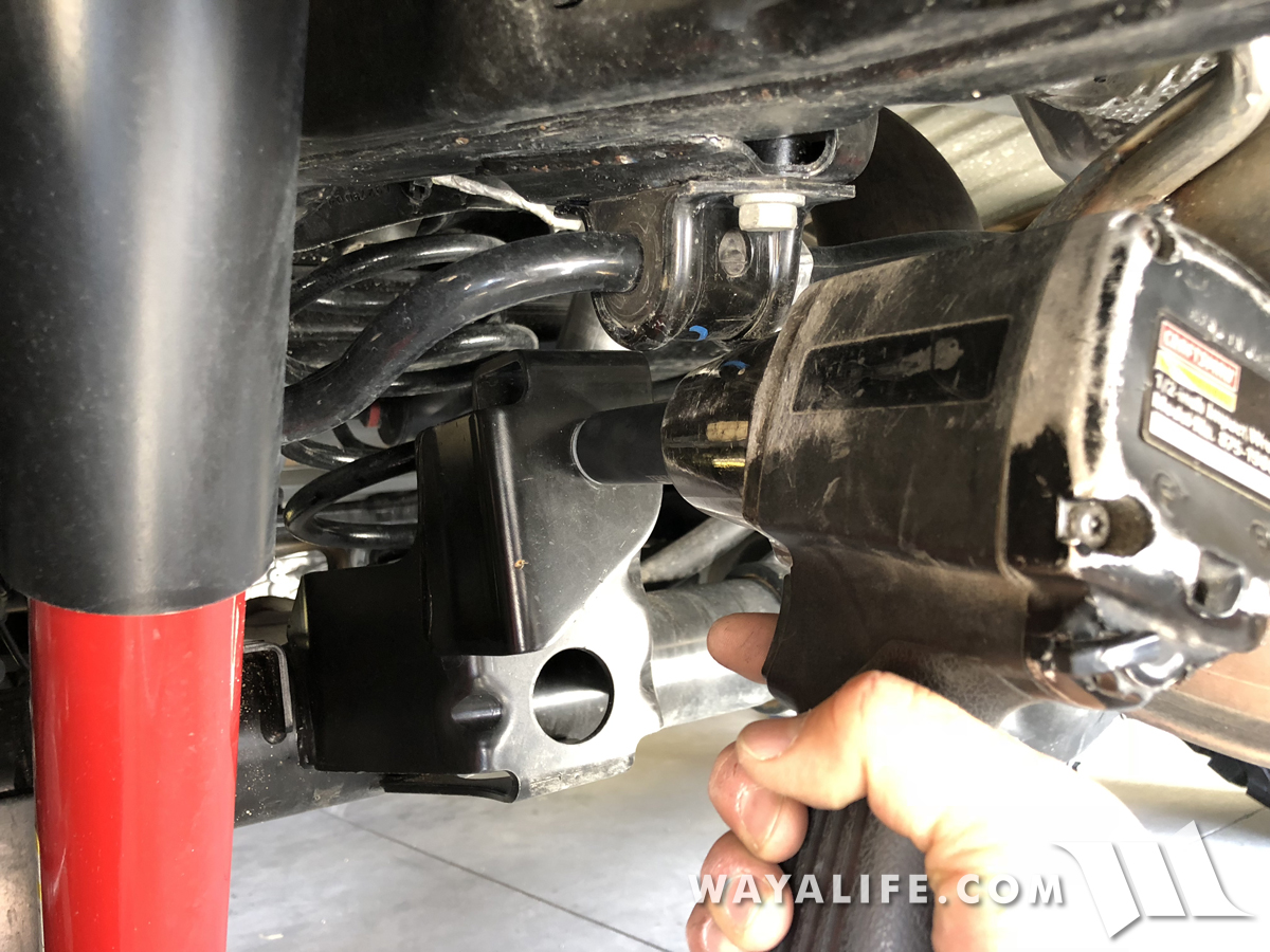
28. Using an 18mm socket and wrench, remove the bolt and nut securing the driver side upper control arm fork to the axle mount.
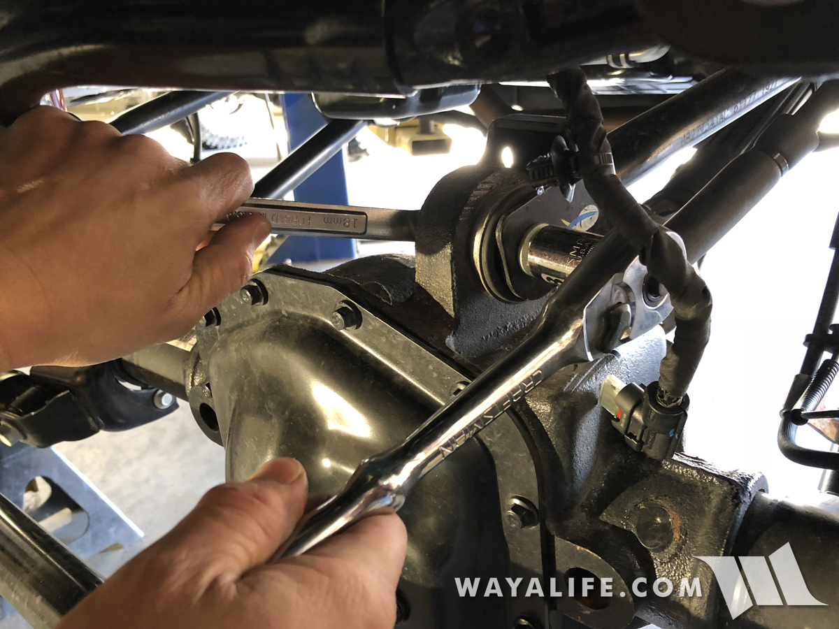
29. Again, using an 18mm socket, remove the bolt and flag nut securing the driver side control arm to the frame mount.
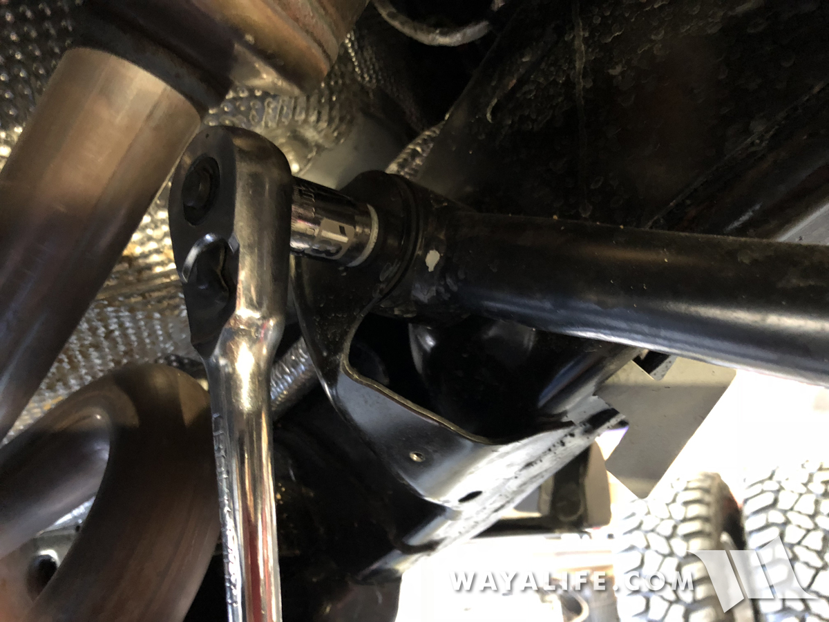
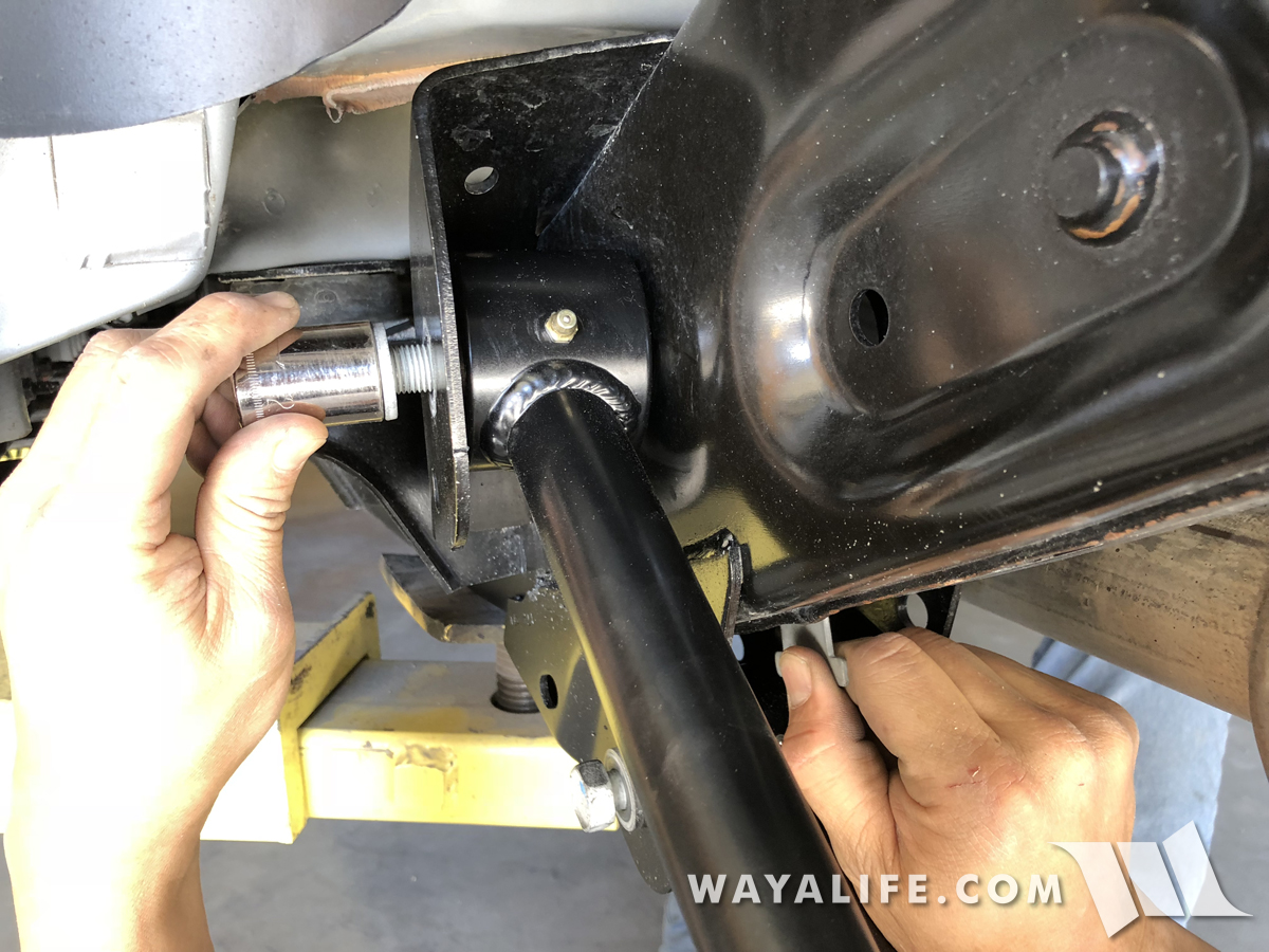
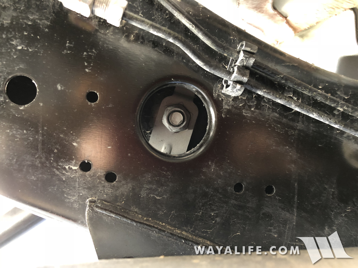
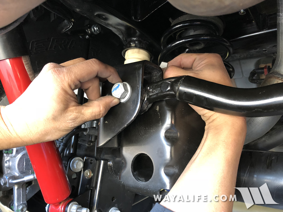
30. Making sure that the zerk nipple is pointing downward and that the bend in the arm matches the factory arm, install your new driver side EVO upper control arm onto the frame mount using the factory bolt and flag nut.
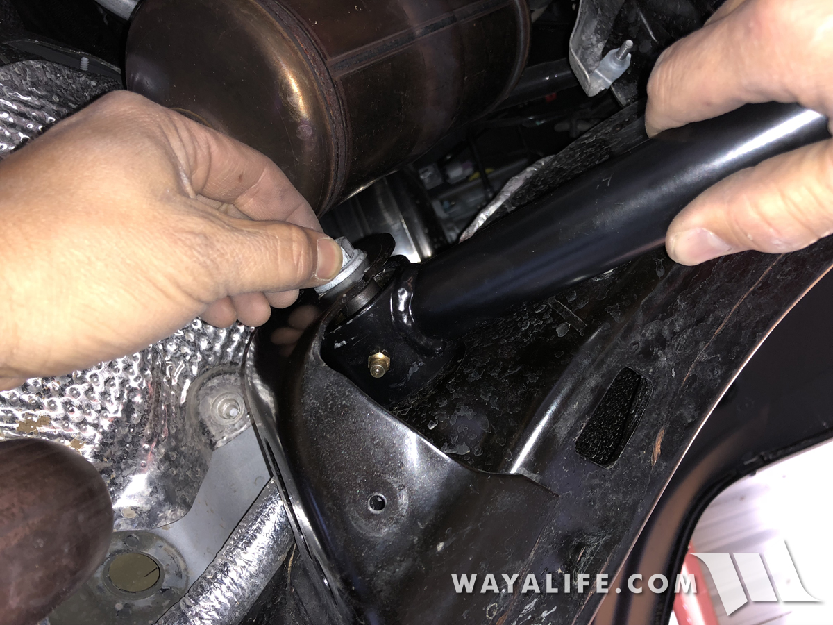
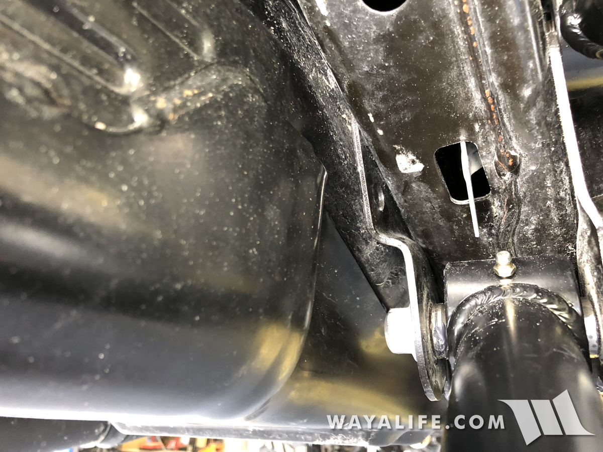
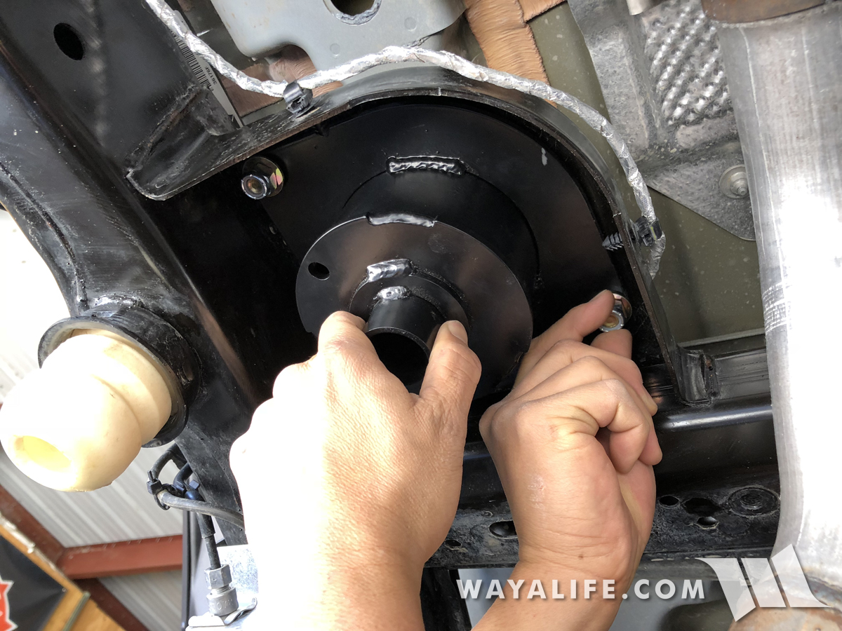
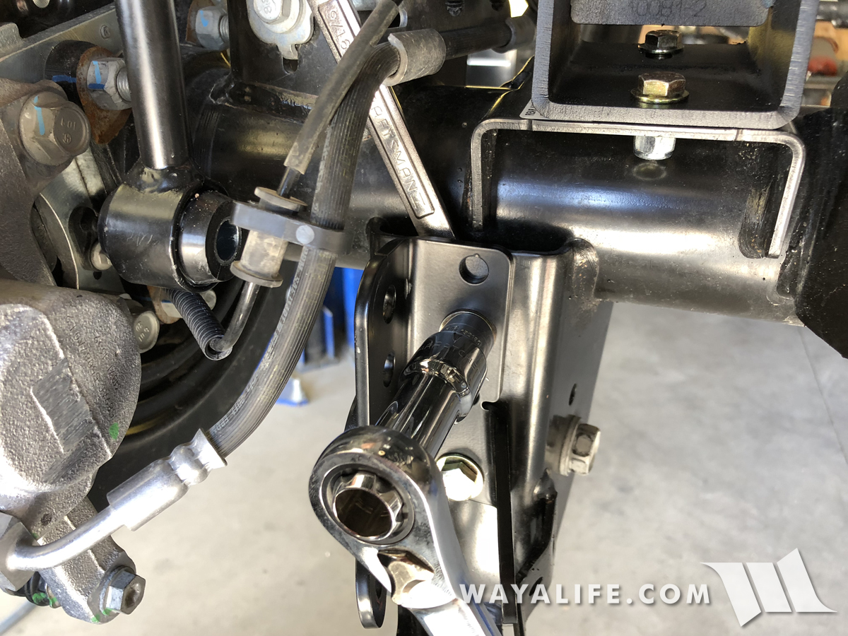
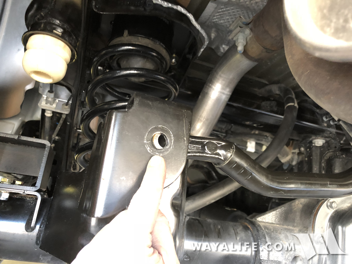
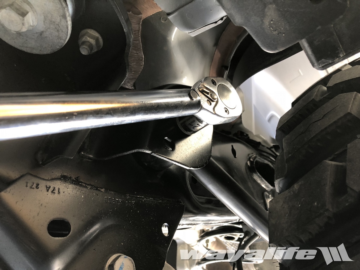
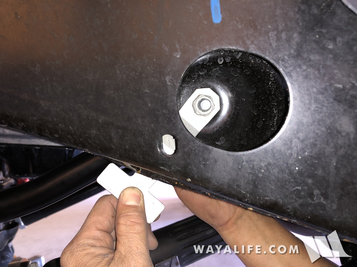
As you can see here, Jeep was nice enough to provide a viewing port in the frame rail to help you get the bolt threaded into the flag nut.
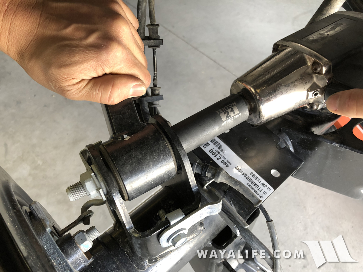
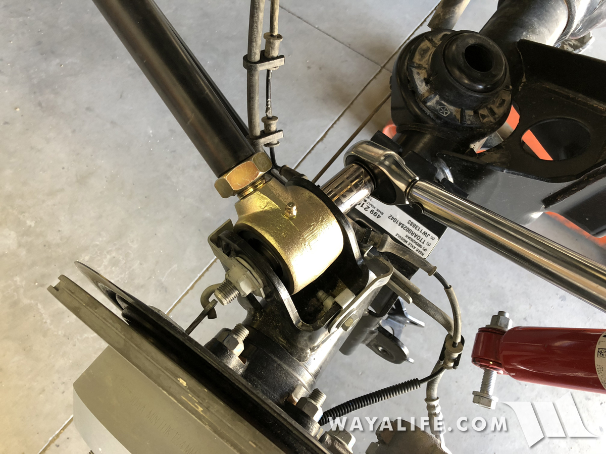
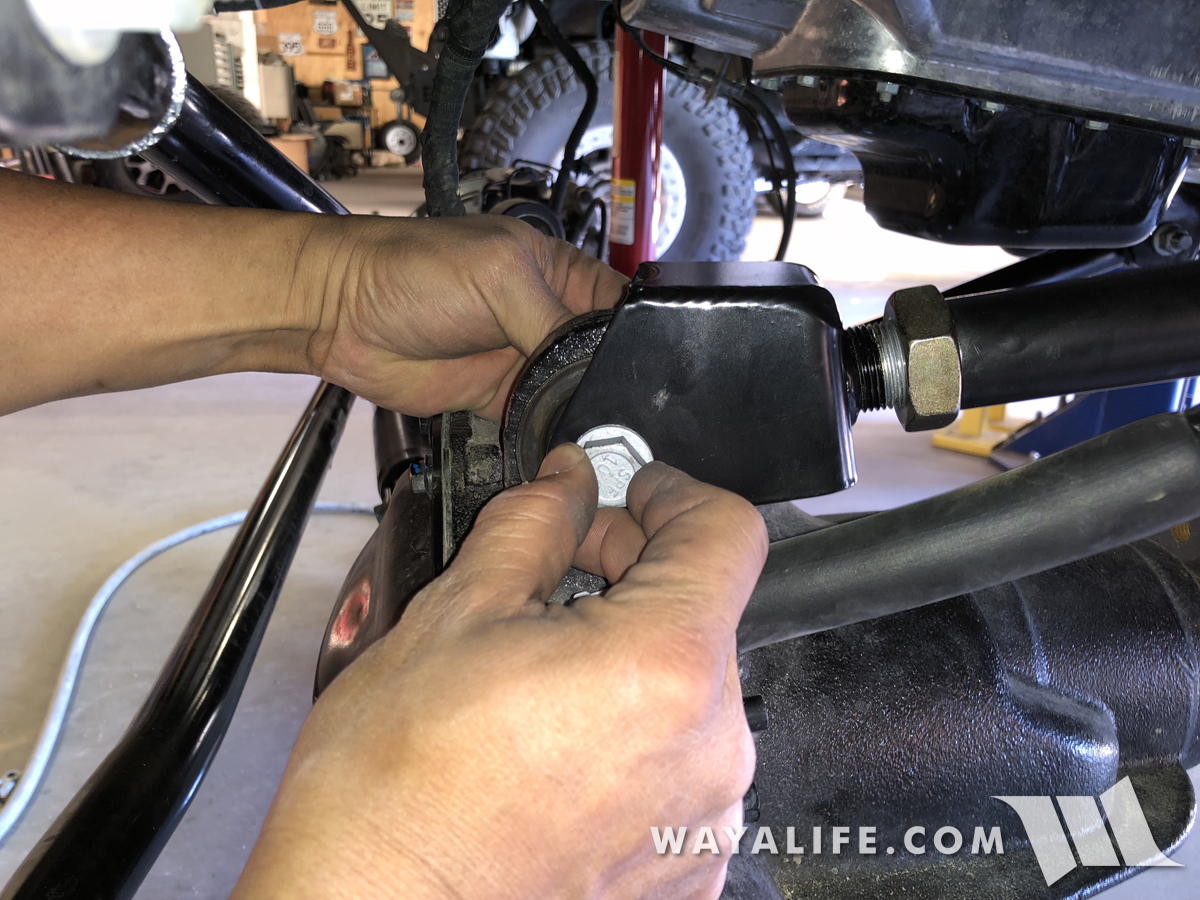
31. Place the EVO upper control arm fork onto the axle mount and secure it in place using the factory bolt and nut. Being that this mount utilizes a bonded rubber bushing, DO NOT tighten this bolt at this time.
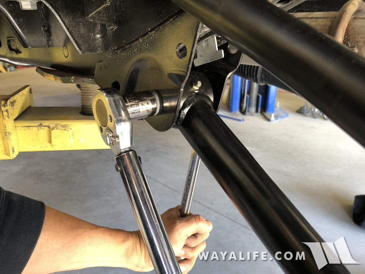
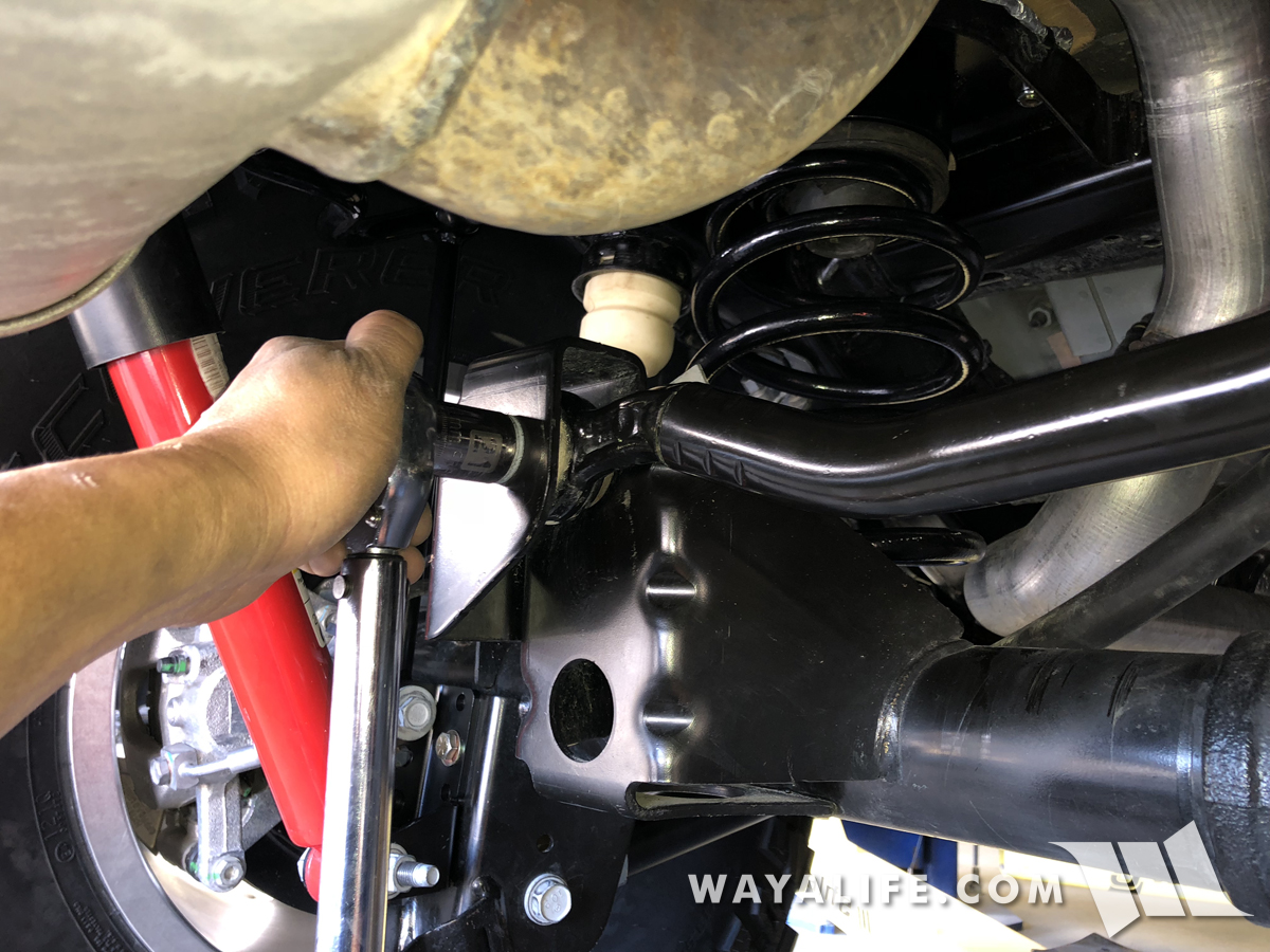
32. Being that the EVO arms do use Johnny Joints and that they won't bind, I would recommend that you tighten the frame bolt to 41 ft. lbs. of torque + an additional 185° now. Once your JL is on the ground, it'll be a lot harder to reach this bolt.
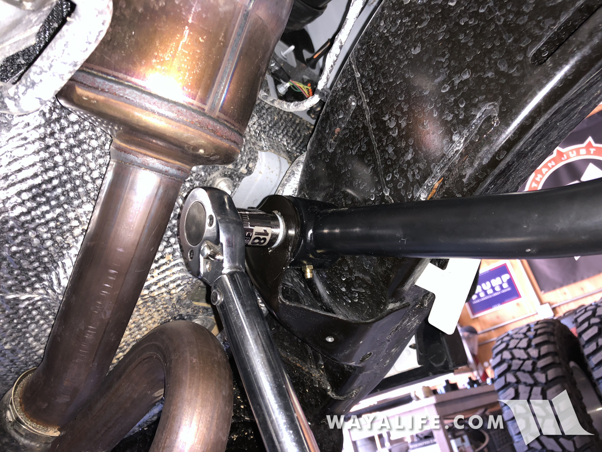
33. Using a 10mm socket, reinstall the factory heat shield back onto the frame side upper control arm mount.
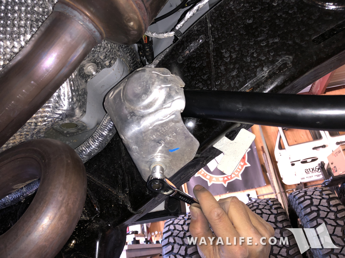
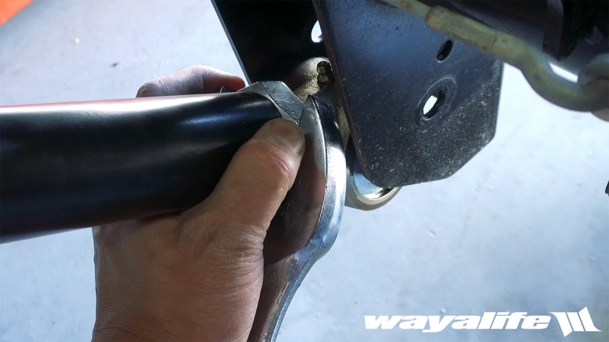
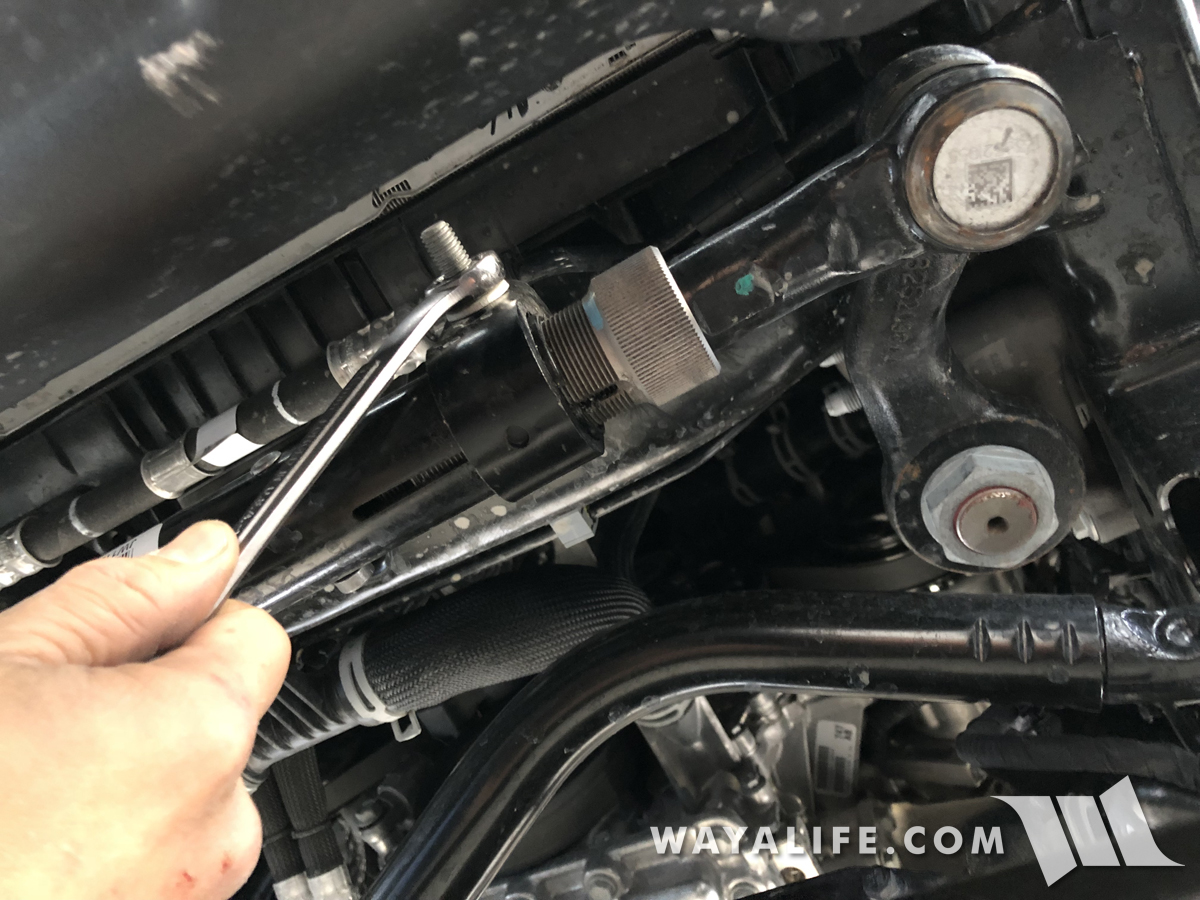
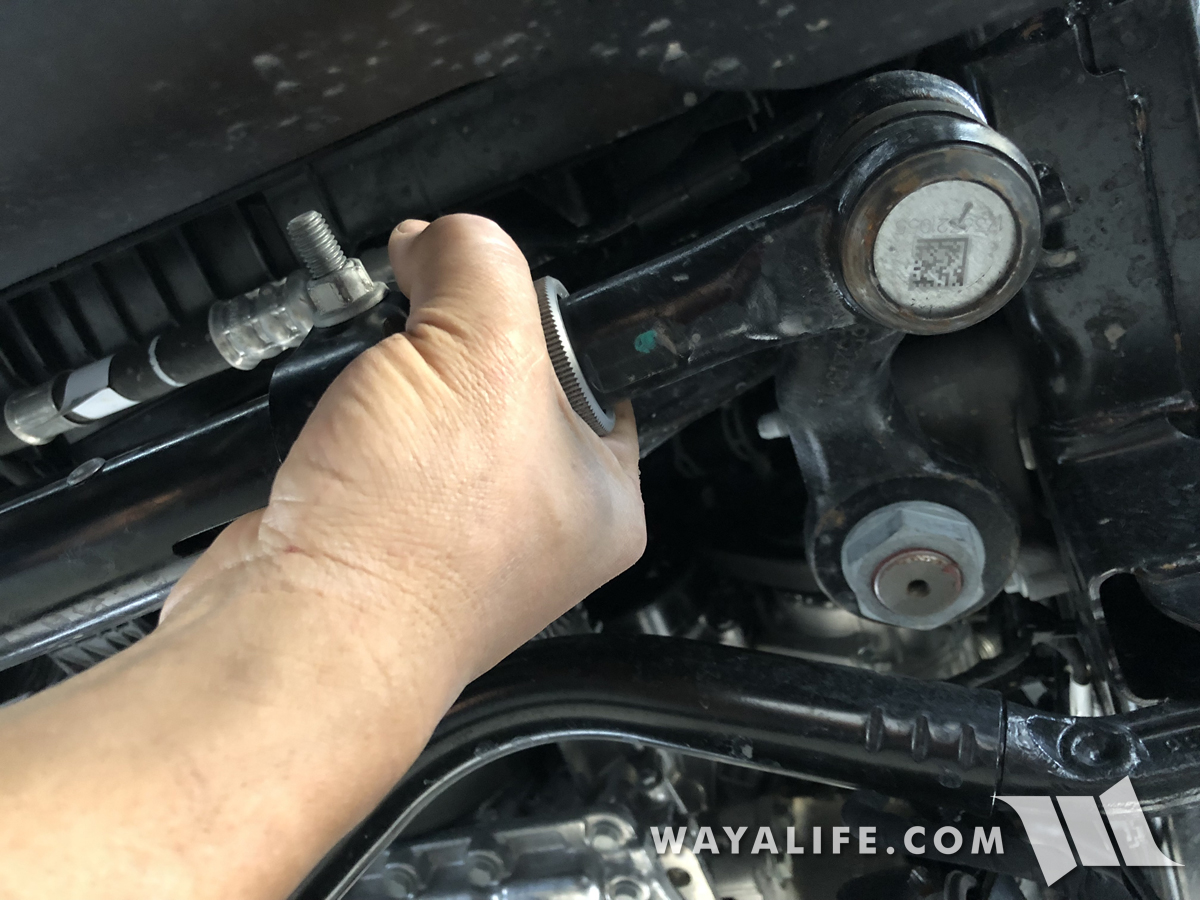
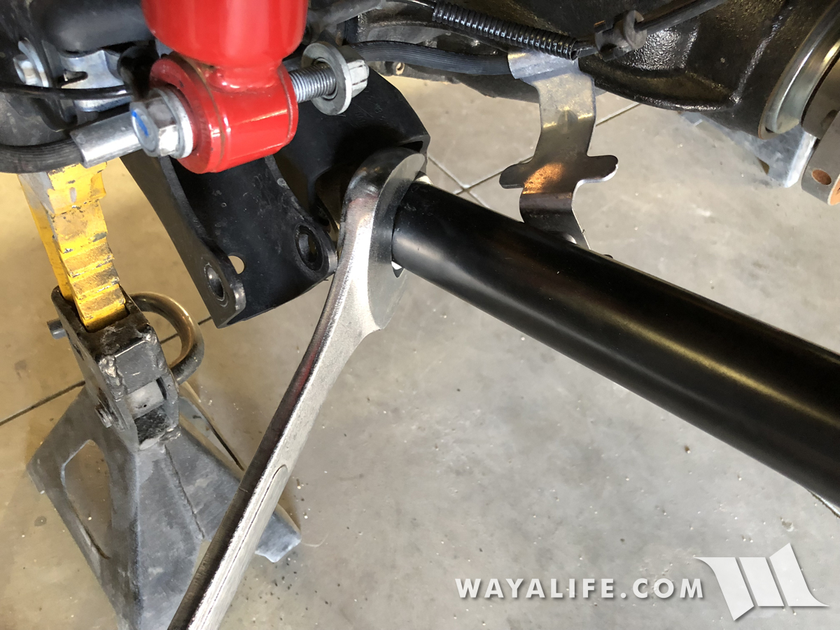
34. Using a 1-7/8" wrench or large crescent wrench, tighten your EVO lower control arm jam nut.
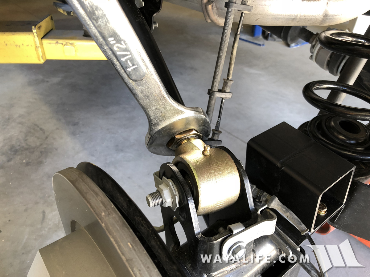
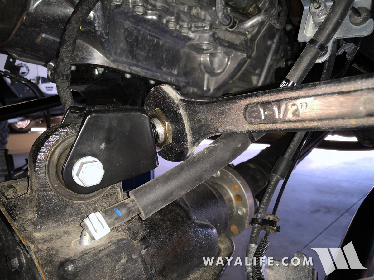
35. Using a 1-1/2" wrench or large crescent wrench, tighten your EVO upper control arm jam nut.
36. Repeat Step #27-35 on the passenger side of your JL.

If you've got a Jeep JL Wrangler and are wanting to install a small lift on it, this installation write-up will show you just how easy it is to do. For our purposes, Cindy and I decided to get an EVO 2.5" Stage 4 Boost Lift or 'coil spacer lift', as it comes complete with 2.5" coil spacers, bump stop extensions, shock relocation brackets, a new pair of rear sway bar links and front brake line extension brackets. Basically, everything you'd need to run a set of 35" tires on a Sport or Sahara or 37" tires on a Rubicon. Being that we are anticipating making more changes in the future, we also decided to get the 8 heavy duty adjustable control arms that are offered as an option as well. With all that said, the instruction you'll find on this write-up will pretty much be the same for most any lift kit of this size and/or type and should still be helpful regardless of which one you get.
What You will get with the EVO Stage 4 Boost Lift
• (2) 2.5" Front Coil Spacers
• (2) 2.5" Rear Coil Spacers
• (2) Front Bumpstop Extensions
• (2) Rear Bumpstop Extensions
• (2) Front Shock Relocation Brackets
• (2) Rear Shock Relocation Brackets
• (2) Front Brake Line Extension Brackets
• (2) Rear Sway Bar Links
• Installation Hardware
Optional Components
• (2) Front Adjustable Lower Control Arms
• (2) Front Adjustable Upper Control Arms
• (2) Rear Adjustable Lower Control Arms
• (2) Rear Adjustable Upper Control Arms
What You Will Need
• 8, 10, 13, 15, 18, 19, 21, 22, 24mm Sockets & Wrenches
• 7/16, 1/2, 9/16, 5/8, 3/4" Sockets & Wrenches
• 1-1/2, 1-7/8" Wrenches
• Large Crescent Wrench
• Ratchet
• Short Ratchet Extension
• Long Ratchet Extension
• Ft. Lb. Torque Wrench
• Vicegrips
• Floor Jack
• Jack Stands
• Pry Bar
• Hand Drill
• Unibit or Metal Drilling Bits
• Cutting Oil
• Trim Pry Tool
• Dykes
• Hammer
• Duct Tape
• Antiseize
• White Lithium Grease
Preparing the Optional EVO Adjustable Control Arms
If you purchased any or all the heavy duty adjustable control arms that EVO offers as an options, the following information will help you to set them up and get them ready for installation.
1. To begin, take a control arm and remove the adjustable Johnny Joint from it.

2. Rotate the jam nut down a bit, apply antiseize to the threads and then work it in by rotating the jam up and down through it.


3. Reinstall the Johnny Joint and repeat Steps 1-2 on all the other control arms you got with your kit.

4. The length of the control arms will all need to be set. EVO does provides measurements for this but it should be noted that these are just starting points and addition adjustments may be required. To begin, take the front lower control arms and set them to 24-1/8" measuring from eye to eye (center of bolt hole to center of bolt hole).

5. When the control arm is set to the proper length, both zerk nipples should be pointing in the same direction as can be seen in this photo.

6. With the control arm set, tighten the jam nut by hand just to keep things in place.

7. Being that the front axle has bushings pressed into the upper control arm mounts, the adjustable front upper arms will have forks instead of Johnny Joints. Again, as an initial starting point and measuring from eye to eye, set these arms to 20-1/4". You'll want to make sure that the open end of the fork is facing the same direction as the zerk nipple on the opposite end. Once set, tighten the jam nut by hand for now.

8. Measuring from eye to eye, the adjustable rear lower control arms should be set to 19-3/4". Again, double check to make sure both zerks are pointing the same direction when set and hand tighten the jam nuts for now.

9. Last but not least, set the adjustable rear upper control arms to 17-1/2" measuring from eye to eye. Verify that the zerks are pointing in the same direction and then hand tighten the jam nut.

You're control arms should now all be set and ready to be installed.
Front Installation Instructions
1. Unless you have a lift, you'll need to start this install by parking your Jeep JL Wrangler on a level ground, apply your parking brake and chock your rear tires.

2. Starting from the front of your JL, use an 18mm socket and wrench to remove the bolt and nut securing your driver side front sway bar links to the lower axle mount.

3. The passenger side front sway bar link is tied into the track bar mount and utilizes a flagged nut to help secure it in place. Because of this, you will just need an 18mm socket to remove the bolt.

4. Using a 21mm socket, a long ratchet extension and a breaker bar or impact wrench, remove the bolt securing the front track bar bolt to the axle.

5. Raise the front end of your JL Wrangler from the axle using a floor jack and then set the frame rails onto 2 jack stands, each placed just behind the transmission skid bar. For our purposes, we have a lift and are racking up our JL Wrangler but as you can see, the arms are still positioned in the same location.


6. Use a 22mm socket to remove the lug nuts securing your front wheels to the axle and then set them aside.

7. Use your floor jack to carefully lift the front axle just enough to help support the weight of it. You do NOT want to raise it to the point where your frame rails lift off the jack stands.

8. Using an 18mm socket and wrench, remove the bolts and nuts securing your shocks to the axle mounts.

9. Use a 10mm socket to remove the bolt securing the brake hard lines to the frame rail.

10. Use a 15mm socket to remove the nut securing the brake hose and speed sensor wiring to the lower control arms.

11. Use a trim pry tool to separate the push tab securing the locker wiring harness to the driver side upper control arm fork.

12. Again, use your trim pry tool to separate the push tab securing the locker wiring harness to the inside of the frame rail.

13. Unplug the front locker wiring harness by squeezing the gray locking tab and pulling straight back.

14. Moving over the passenger side, use a trim pry tool to separate the push tab securing the FAD wiring harness to the passenger side upper control arm fork.

15. Again, use your trim pry tool to separate the push tab securing the FAD wiring harness to the inside of the frame rail.

16. Unplug the FAD wiring harness by squeezing the red locking tab and pulling straight back.

17. Use your trim pry tool once again to separate the push tab securing the FAD wiring harness to the back of the unit.

18. Using your floor jack, slowly lower your front axle making sure that there aren't any wires or components getting hung up. Continue to lower your axle to the point that you can simply slip your coils out from their perches.

19. Remove the upper spring perch rubber isolators by slipping it down and off the bump stop towers. Set them aside for now as they will be reused.

20. If you are installing new heavy duty adjustable control arms, it'll be helpful to support the weight of your front axle with a couple of floor jacks or jack stands as shown here. I should note that this is not required but it will make things easier to work on.

21. Remove the bolt and nut securing the driver side front lower arm to the axle mount using a 21mm socket and 24mm wrench or large crescent wrench. An impact wrench or breaker bar will be required for this job.

22. Again, use a 21mm socket and 24mm wrench or large crescent wrench to remove the bolt and nut securing the driver side front lower arm to the frame mount . An impact wrench or breaker bar will be required for this job.

23. Making sure that the zerk nipples are pointing upward, install your new EVO front lower control arm onto the frame mount using the factory bolt and nut. I should note that the 16mm bolt will make for a tight fit and you'll need to encourage it through by giving it a few taps with a hammer.

24. You will now want to install the EVO front lower control arm onto the axle mount using the factory bolt and nut. Again, it'll be a tight fit and a few taps with a hammer will be needed to help it through.

25. Being that the EVO control arms use Johnny Joints, you can now tighten the bolts to 103 ft. lbs. of torque + an additional 50° but I would still recommend that you do a final torque check once the full weight of your JL is on the ground.


26. Repeat Steps #21-25 on the passenger side of your JL.
27. Moving over to the front upper control arms, use a 10mm socket to remove the 2 bolts securing the heat shields to the frame mount.


28. Using an 18mm socket and wrench, remove the bolt and nut securing the driver side upper control arm fork to the axle mount.

29. Again, using an 18mm socket, remove the bolt and flag nut securing the driver side control arm to the frame mount.

30. Making sure that the zerk nipple is pointing downward and that the bend in the arm matches the factory arm, install your new driver side EVO upper control arm onto the frame mount using the factory bolt and flag nut.

As you can see here, Jeep was nice enough to provide a viewing port in the frame rail to help you get the bolt threaded into the flag nut.

31. Place the EVO upper control arm fork onto the axle mount and secure it in place using the factory bolt and nut. Being that this mount utilizes a bonded rubber bushing, DO NOT tighten this bolt at this time.

32. Being that the EVO arms do use Johnny Joints and that they won't bind, I would recommend that you tighten the frame bolt to 41 ft. lbs. of torque + an additional 185° now. Once your JL is on the ground, it'll be a lot harder to reach this bolt.

33. Using a 10mm socket, reinstall the factory heat shield back onto the frame side upper control arm mount.

34. Using a 1-7/8" wrench or large crescent wrench, tighten your EVO lower control arm jam nut.

35. Using a 1-1/2" wrench or large crescent wrench, tighten your EVO upper control arm jam nut.

36. Repeat Step #27-35 on the passenger side of your JL.

