LED Light Upgrade for your Power Window Switches

jimcob

New member
*UPDATE 7/12/17*
Some source links for the photos below are missing from my original post. See post #49 for the same write-up complete with photos.
*UPDATE 7/12/17*

8wiNcC9s70aaJdQNyzGm6nAq8cEea-O183BPpbQW8OFrd1TEwqle5gxA8opj16q7RLOpyjXMmXP-uFy64GnBg2vL4vY1j4k_qbIgMlW_7qyzG8C2jtxlXZIZB2xoskLwlfkdZDOUAb-nzSZAXv2frJxE2SWEnAIysDKpN3QIEZqFeswQfpdcHPUzQtiqYymbkgeqA9w1guqyW3FTUTpRx32jg3tPCmlxUrwrNFV6ll3nHZUAI6Q2NIqZK9eEUsEFKUF8y9e8DT6eV5Ti5R0QA_97nLP5QtQj_X3qS5wsZFngNIqc0-B3MJC6AimOUaMXmlYu2bcapNrCrYCdQrRdLBPI8ZVuyNyCUYqAbPyNHBg8phtX1Y9DVf_zzK4DdlDmJzphpjFfRxWHey-1Ck2Ypv25BavFII0kREmQFS4pamUMobopeiM2PdQaAfmOYZRkrhhh2slfcBMaoCVJvJwSR_-vDYgb72H9jaFeeF61tdN9ixZ-9XbI1SenAA2Xp5PK7qzsjBYyDZA3sfO1hl9Wgkt7fH4CGXDTTP6obMhDBI45Bfm388tdstPZSpIAhD6E6BvvFPkVWsuYMeJVYAFXyyMKOLYZ-P4cjF0idmJEYIJIWCz7eTgziQPGu417fKXQ-52xEWFerTf05NOPqZWeMT3JqBBVwUm4MvIqeqo=w640-h480-no


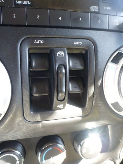
About 40,000 miles in, the back lights on my power window switches started to burn-out. Being OCD, I could not stand the fact that my switches were not uniform in the dark. By the second burn-out, I decided I had enough! And the madness would not continue! I decided to crack open the Power Window Switch Module, and replace the incandescent lamps with some long lasting LEDs. Here’s a write-up on how I did it.

I decided to use Cool White LEDs. There are actually blue filters built into the switches to “color correct” the stock incandescent lamps to the factory green you see.

Yellow (Warm Light) + Blue (Filter) = Green

So the Cool White LEDs I chose now give the switches a nice blue light. If you wish to keep the stock green light, I would suggest buying the Warm White LEDs or even the Yellow LEDs to impersonate the warm light you would get from the stock incandescent lamps.

If for some reason you completely mess up and break the circuit board, here's the Part Number (68057595AC) for the Switch Module. It'll run you about $55-$75 online.

TzOY2CsNQTnGEh8TL_KoOB5xKfOkDpuXvJvYIyHyulCVuep7MGcexP6YyyjoB_UIDanLJnD-fO5hvTQ0NQT2o5S4ooTpta3Wk-pSUbryP8xpJBqA6mglJBChZwF53TOe44EfvyladjUzvwpKq9kdpUyWg7SFqIVbxTsXbh4UP06Q9khmDt7GTkeP6vihTGWK5QEqTH_ejVghSyia6VvcO8rBN5gBina9aQpANwhedxwZKmZXTJ3SpZ43i4Je1mGPTl-9qmOrA2goDVpIiKwtNJWQ6-IPOpIfyJbKQDd61ctVyWkY-INA-0txpAO8EGcEtwQLrDKRguSD7baHMui12TAWC_K9AqRb87iuEqJNL_clFzpwbjuGgw3QZr_PmNocS5K4rRHtYjKMugZrZKqoCLKXEuMMhhAjtL-frDvW8vzNYIF7D8MdP9l-5ZmAPDaQHGh65zRtR0JFIvcAyugeoiB1kP4Mg1yi20A4dYl81An0aOodOtuHnbhHY8StfCEbZzmS8E_QG8SPFzVK-sf-q1qD65EH0sXWcK6dlDj_yB4XdTGNs6AD3K1HOD0KL9kt5OOcNVkSXcWsUybt-1Oa_iOiro7Fb1_kh62-JF8J9CZflA=w640-h480-no


What you need:
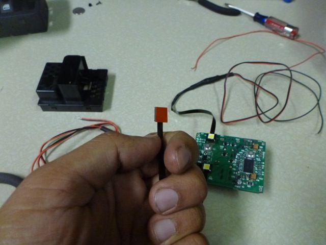
(4) Surface Mount LEDs from Oznium

_DkiOtLl0ZuGQ3KDUe1IAN_3NQi-YW848senvsQrok4_J4xzY6RcFfZCPRK3169btA9Qf76LXTOdqVRaJPazxi7DlrhyeMz_zedmv49VVGm9ME_f7FgTTBavrOD8EIKAIIjYZyaEHaB3w7zIGsKxtP77SxxYtYvQVTZO84vlqd2VdYp08T7jZ74kDOQaQYrc379AfNucPw7FYDKSdtx9EmMmMwXoQxqH1NJG2Ky1H3nEaFf85er37wM8WXOTCW412n2Tf-jpnIk7jWseRjyBvqiY4uNgqh6YCVHUjMf3ZIbMU6S6D8jjWDnnfpLC4xEYjrKAefs_rzv62FwY81LN8doFXFf5DZ7oFsFZUT6XMGnQmulSz3OWhOKCPFjZ3zPUwmdjQp0eV34SE-k_50znkG-kI39a8OeMzLohynk-6O71l0aCNBmRg7m-GNi5T_yQsuAWnOT_Mzd_LEUXvm-zg7zRUlPfrtZ6eo8f-Afhomb8iW67redph5uTWvnr97NSgROteQ3E093_0_35ETLwGZV5e8I_gXTCJEnLgLkswn5t3Hz8tqm3zFi1F-dCAfNSLWlX6dKi-rx7URgY87rG71-aqJ7vhMqxmKBc81lVg5hgPA=w640-h480-no

-4NY8MNRA0q4yCzjqW93LH_Uxp_2AC_9kxTyVtV4T7k7wMNTChhmXCXxeUMqObvzik6XOhfJoquubBFdb0rvSRt-7dNF60wAPd0JRpLh9RDSjXV4hTE8FpTRbVPLtSQ8wt0Ud1mYacgB7eE_hOlxQo7IVEtXbJhWlrKsppqV-M4ouSXr92lFF0IFpzVEIv-5zE47ogRUZjDkyz4y0Ng8G6JeGgVv5JSq8LvA6R5BU91mWWpicDSHvb740zLGCUioQXbXJfGkkOhRh1oFzpghaUPCETqF8oyKOuf2ZR_UPOliuMqgIzhwfEwNk7QRFyIAPrN0AGjn_OO9bJySpErXXiuotEuKL851hAyINgeKRv6WsjfLMXr9lM7ybTcxvfgAjpdEixGucEDMBTJJ_w3vUoO2tOWnI7T-bEzbaDVMO_YhWM7r0xSshEG-WGuq9qS6cGge1AOdftD9W6BUBTplP1qGw745R75qQTJ3fRg1suvEVGsoHWfxvtpn1t30Df25aRek5GFf5_DNLuMTFiJ7cnqlEjLurwCBjiSWU_H1aIzRNj4JvWqbaID8X8K7xfDV694ZtVAymLebyZrHtdHD0YboDgLI-JvmrubRlD_-T-kzEg=w640-h480-no


(6-12”) ¼” Corrugated Tubing
(1) Spade Connector
(1) T-Tap Connector
18 Gauge Wire
Small ZipTies
Heat Shrink
Soldering Iron
Solder
Solder Wick
Small Flat Head Screwdriver/Pry Tool
Small Wire Cutters
Wire Stripper
Crimper

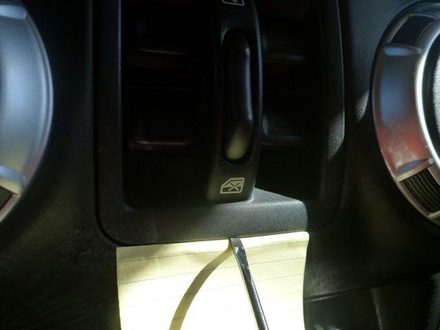
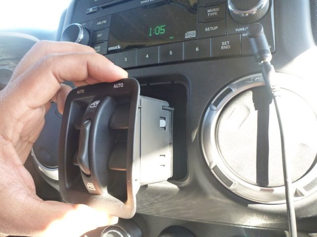
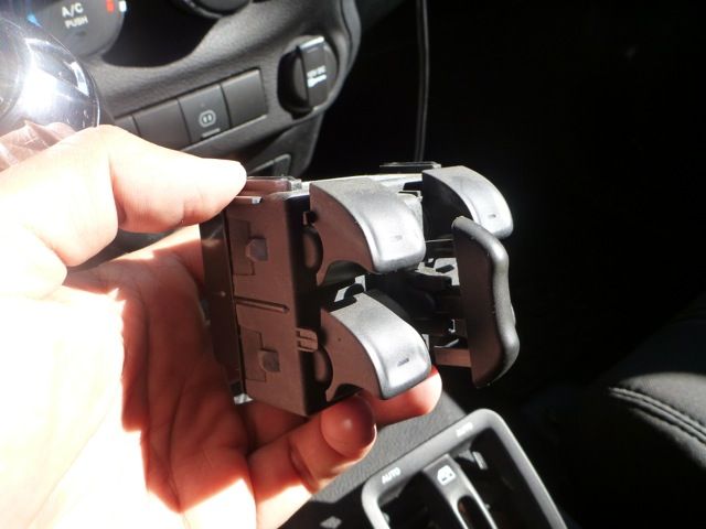
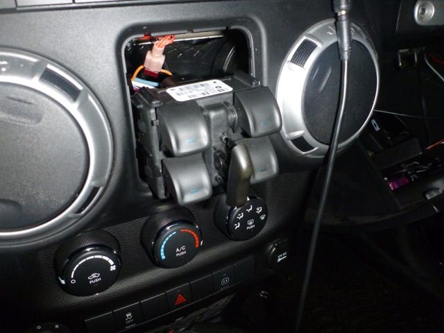
1. With one hand, pinch the Window Lock Switch with your thumb and index finger, and pull up and out on the Switch Module. This will make a bigger gap for the screwdriver blade to fit at the bottom of the Switch Module Front Cover. While pinching the window lock switch, simultaneously pry the bottom of the Switch Module Front Cover with a small flat head screwdriver until the Switch Module pops out. I used a small piece of paper just to protect the dash from some minor scratches.

P1030059_zps3bfa5a0c.jpeg

P1030061_zpseaab47fa.jpeg

P1030065_zps68ba9999.jpeg


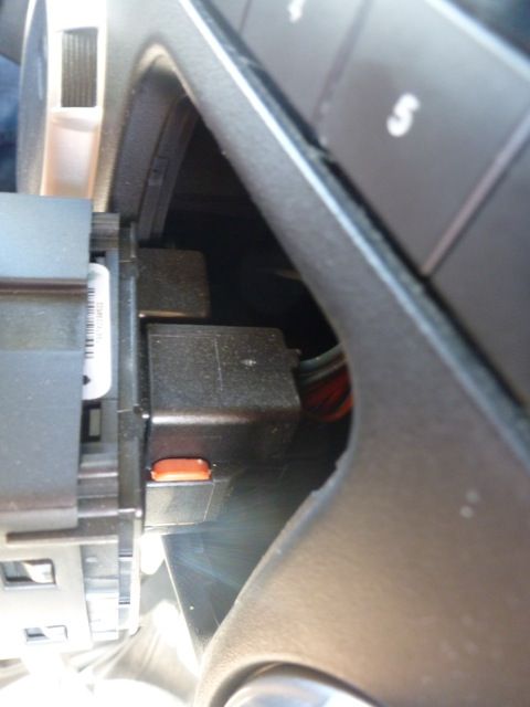
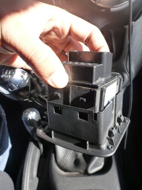
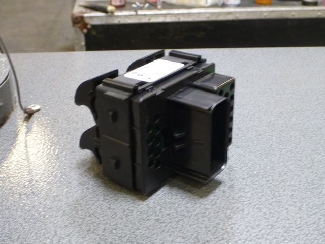
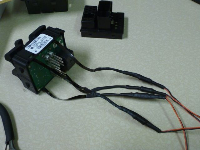
2. On the back of the Switch Module is a red tab. Pull the red tab up, and squeeze the release tab to free the Switch Module from the wire harness.

P1030063_zps45bd0029.jpeg


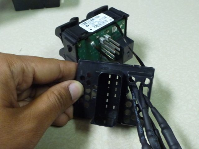
3. There are four tabs (two on each side) attaching the Switch Module Front Cover to the Switch Module itself. Use a small flat head screwdriver to pry each tab of the Front Cover off the Switch Module.

P1030066_zpse67fb75e.jpeg

P1030067_zpsb04fe007.jpeg


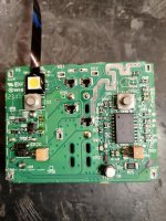
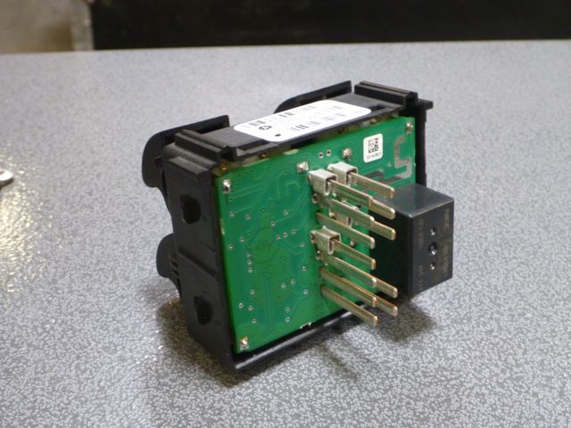
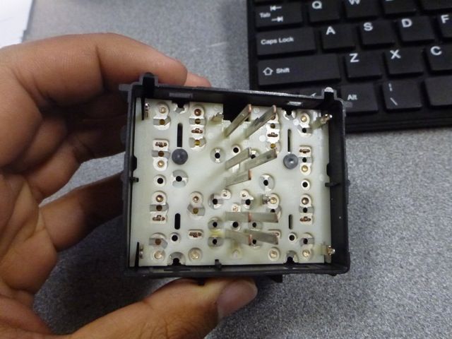
4. There are an additional four tabs (two on each side) that keep the Back Cover of the Switch Module attached to the Switch Module itself. Just like with the Front Cover, use a small flat head screwdriver to pry each tab of the Back Cover off the Switch Module. With the Back Cover off, you can now see the “Pin Side” of the Switch Module circuit board.

P1030075_zpsdfdc76db.jpeg

P1030073_zps9b7da171.jpeg


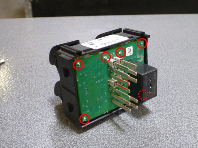
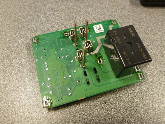
5. The circuit board is attached to the Switch plate by 7 soldered anchor points. Using a soldering iron, desolder these points to free the circuit board from the Switch plate. Some solder wick will be helpful to help pull up excess solder during this process.

P1030073-edited_zps7d204450.jpeg


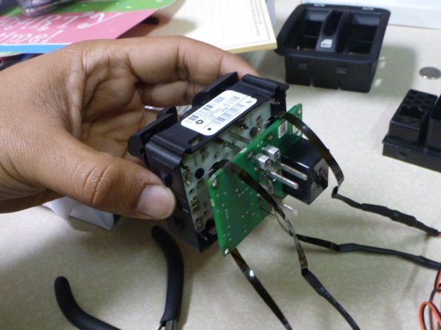
6. With all 7 anchor points desoldered, you can now carefully separate the circuit board from the Switch plate. This may take some wiggling.

P1030077_zps1195a821.jpeg

P1030079_zpsa8f95697.jpeg


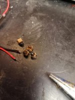
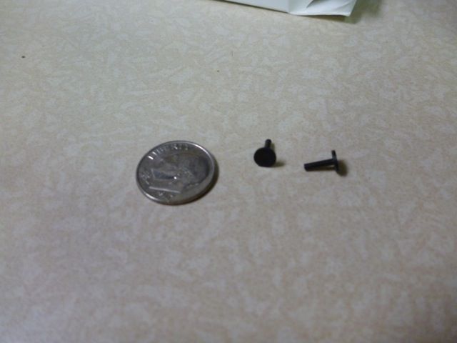
7. Be careful not to lose the 2 very small “push pins” on the Switch plate. These easily fall out, and I actually lost one. Had to retrace my steps to find. As you can see, they’re smaller than a dime. I put these aside when working on the Switch Module. If you loose these pins, you won’t be able to auto roll down your front windows with a single click.

P1030091-Pins_zpsf886f48f.jpeg

P1030081_zps6ae8ef88.jpeg


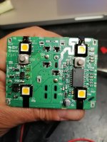
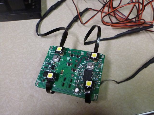
8. Flip the circuit board over, and now you can easily view the 4 incandescent lamps that backlight your Power Window Switches. I decided to “cheat” here a little bit, and not actually replace these lamps, but mask them. The Surface Mount LEDs conveniently have an adhesive back. Peel back the red backing, and stick the LED directly on top of the incandescent lamp. Or if you wish, you can remove the stock lamps all together and place the new LEDs in the same location. The switches will still work fine. For fear of messing up the circuit board, I decided to just leave the stock lamps there.

P1030078_zpsa8dcda4f.jpeg

P1030089_zpsa873c76a.jpeg


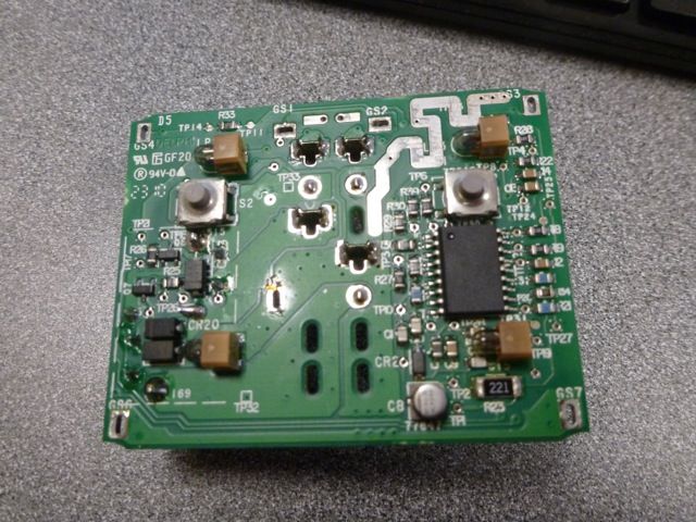
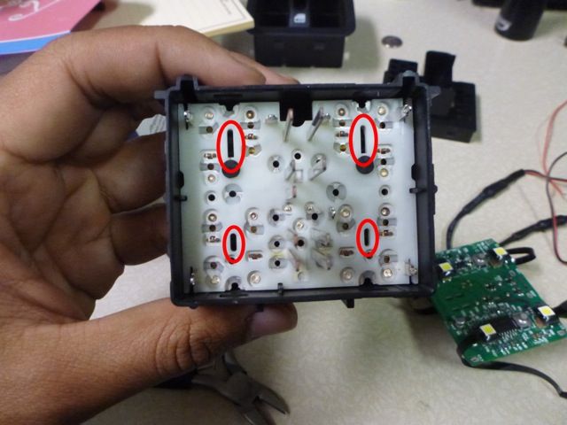
9. Be careful to be as uniform as possible with your placement, as ununiformed placement will cause variations in intensity as the light filters through the switches. Try to line up the center of the LEDs with the open slots on the switch plate. Shown here.

P1030090_zps3b50bfcd.jpeg

P1030091-slots_zps545c764b.jpeg


10. With all the LEDs mounted, it’s time to start the reassembly process. Feed the circuit board back on to the Switch plate being careful to make sure all the wire webbing is organized and flat.

P1030093_zps1d6511b7.jpeg


11. Once the circuit board is back in place, resolder all the anchor points. You’ll notice that circuit board will sit a few millimeters higher than before due to the LEDs, but they will fit fine. Just be sure you can still resolder all 7 points.

P1030094_zps332b61ae.jpeg


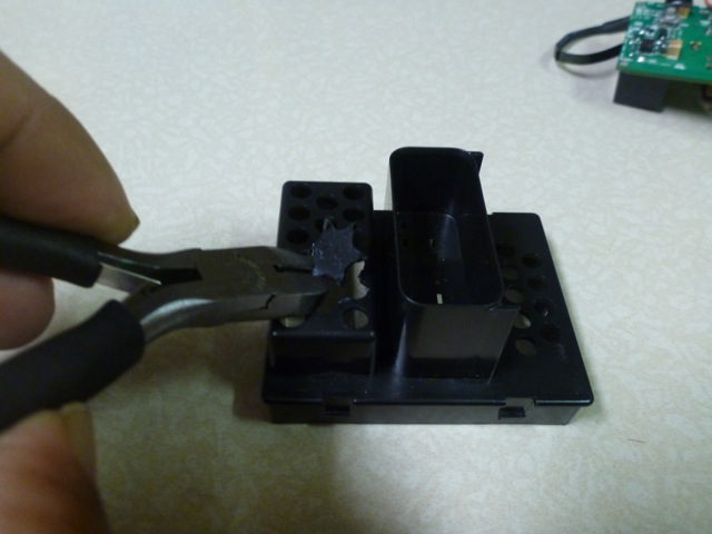
12. Use small wire cutters to make a bigger hole in the Back Cover to feed the LED wire leads through.

P1030083_zps9b92d38f.jpeg

P1030085_zps2631f373.jpeg


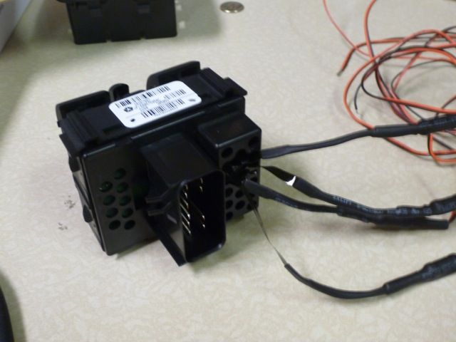
13. Once the wire leads are fed through the hole, reattach the Back Cover to the Switch Module until it clicks into place. Again be careful to make sure all wire webbing is organized and flat before snapping the Back Cover back on.

P1030098_zpsf9a0c852.jpeg

P1030099_zps9de4fd79.jpeg


14. Now you can begin to make your LED wire harness. The LEDs will come with about 36” of end wire. I decided to cut this down to 8-12”. Split the Positive from the Negative leads, and strip all ends. Splice all the Positive leads together. Then splice all the Negative leads together.

P1030100_zpsfd5e6d41.jpeg


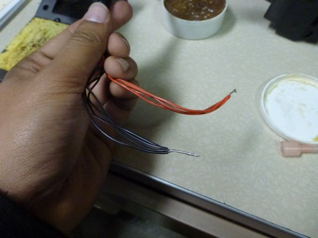
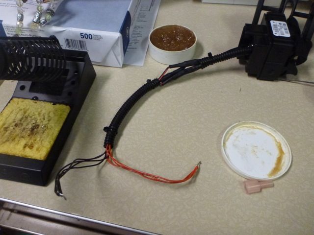
15. I used ZipTies and Corrugated Tubing to clean things up a bit.

P1030101_zps7203e5b5.jpeg


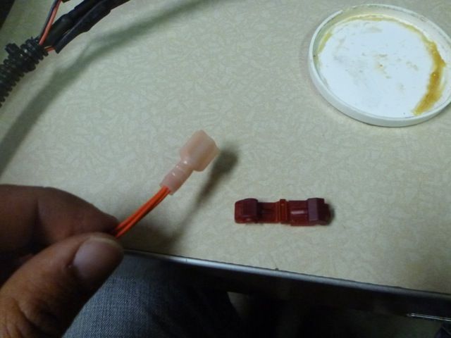
16. Crimp a Spade Connector to the Positive lead.

P1030103_zps7aa7687b.jpeg


17. Splice a few feet of 18 gauge wire to the Negative end. Make sure to have enough wire to reach a Grounding point of your choice. I used the Grounding point on the passenger’s side footwell.

18. On the wire harness, add a T-Tap Connector to the Orange wire with a Gray stripe. There are two Orange with Gray wires on the harness, tap into the smaller gauge wire. If you’re looking at the connectors of the wire harness, it’ll be the second pin down from the top on the passenger’s side. Again, Orange wire with Gray stripe.

P1030105_zpsa82fc427.jpeg


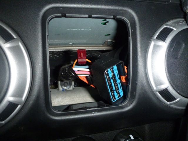
19. Connect the Spade Connector to the T-Tap, and hook-up your Negative to a Grounding point.

P1030107_zps11e57790.jpeg


20. Reconnect the Switch Module and the wire harness, and lock the red tab back down.

21. Snap the Switch Module Front Cover back on to the Switch Module.

22. Snap the entire Switch Module assembly back into the stock location.

P1030113_zpsc3e36f2b.jpeg


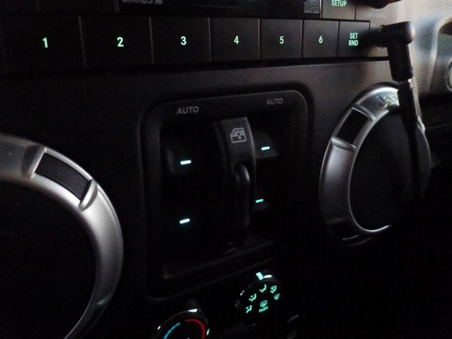
And there you have it! Your Power Window Switches are now backlit with long lasting LEDs with the color of your choice. And best of all, because you tap'd into the wire harness, they will turn on/off and dim with the rest of your dash lights!
:beer:

Hello and Merry Christmas:

I understand that this is quite an old post, so the photos do to show anymore. Would it be possible to send me the photos even on an email?
Thank you!
 

desertbuzz

New member
Amazing write up that I have saved for years .
The moment has FINALLY come to implement it. (I've been living with a dark power windows switch for years now).
I finally got the Oznium 5050 leds as per the write up and will embark on this mod hopefully today.

ONE QUESTION about wiring the the new LEDs:

Tapping power as per the write up, makes future removal a bit difficult.
I'm looking into tapping directly onto the plug for both positive and ground.
Can anyone help here ?

Cheers
 

CalSgt

Hooked
Amazing write up that I have saved for years .
The moment has FINALLY come to implement it. (I've been living with a dark power windows switch for years now).
I finally got the Oznium 5050 leds as per the write up and will embark on this mod hopefully today.

ONE QUESTION about wiring the the new LEDs:

Tapping power as per the write up, makes future removal a bit difficult.
I'm looking into tapping directly onto the plug for both positive and ground.
Can anyone help here ?

Cheers

Wire as shown but add a two lead weatherpack (or other) connector to the additional wires to make removal easy... The way those boards are assembled would make internal wiring to the existing connector pins very difficult

weatherpack_large.png
 

CalSgt

Hooked
I thought about it some more & it may be possible to unsolder the incandescent lamps from the board and replace them with solder in type LED's. Still pretty tricky and would require some skill and determining the polarity of the board before attaching the LEDS, unlike incandescent bulbs LED's will not work if hooked up backwards as that is the nature of a diode.

components_ledclip2.jpg
 

desertbuzz

New member
I thought about it some more & it may be possible to unsolder the incandescent lamps from the board and replace them with solder in type LED's. Still pretty tricky and would require some skill and determining the polarity of the board before attaching the LEDS, unlike incandescent bulbs LED's will not work if hooked up backwards as that is the nature of a diode.

View attachment 357798

I wouldn't attempt ANY soldering on the board if I were you... Everything is very tight... It is pretty much impossible.
However you can remove the burnt bulbs by simply wiggling them a little.
I did... And stuck the ozium LEDs in their place. It's also a better fit (the board won't sit higher when reassembling.
See pics of removed bulbs and work in progress.
 

Attachments

  • IMG_20210113_142316.jpg
    IMG_20210113_142316.jpg
    121.7 KB · Views: 48
  • IMG_20210113_142655.jpg
    IMG_20210113_142655.jpg
    86.8 KB · Views: 48
  • IMG_20210113_142739.jpg
    IMG_20210113_142739.jpg
    97.6 KB · Views: 50

CalSgt

Hooked
I wouldn't attempt ANY soldering on the board if I were you... Everything is very tight... It is pretty much impossible.

See pics of removed bulbs and work in progress.

To each their own I guess... I wouldn't be afraid to solder on that board
 

desertbuzz

New member
Update (Jan17th 2021)

This is the final update to a successful mod which would not have been possible without the amazing original write-up.
Thanks again @Charlie Mike !

About the LEDs:
I bought the warm white from Oznium.... Which ended up giving a blue light through the switches (as it was mentioned in the original post).
I wanted to keep the factory green, in line with everything else. So I corrected the color by dropping a tiny drop of yellow transparent paint for stained glass with a toothpick on each LED (It's cheap and available @ any arts & crafts or DIY). Excellent result and won't affect the operation of the LED or intensity in any way.
IMG_20210113_145932.jpg

I had this connection from an old RC car laying around. I used rather than a T connector, for easier disconnection in the future.
IMG_20210116_130621.jpg
IMG_20210116_130547.jpg

For power, I chose to keep the factory setup and have these switch lights always on when ignition is switched.
So, for it's positive #12 and negative is #4 as shown below.
WORTH NOTICING : The positive in my 2012 JKU WAS NOT orange with gray stripe as mentioned by Mike. Mine was pink with yellow stripe.

Screen Shot 2021-01-16 at 2.36.28 PM.png

And here is the final result
IMG_20210116_130505.jpg
 
Last edited:

Lawdog82

New member
I decided to tackle this repair without adding the aftermarket wiring. I ordered LEDs from amazon here is the link, Partsam 20Pcs 4.7mm-12v Car White Mini Bulbs Lamps Indicator Cluster Speedometer Backlight Lighting https://a.co/d/ac5bj0s. Switch was then disassembled as per the original post write up. burnt bulbs were removed and polarity was verified at every set of pads. you would think that the polarity would be the same at every set of pads but one is reversed. LED tails were cut to length and soldered to board as per polarity requirement. Boards were then temporarily replaced for testing before soldering switch assembly back together. A dab of hot glue was added behind each led for vibration purposes. I was not worried about the color just being able to find the switches easier in the dark.
ECA2C806-D11F-40F8-95F9-7BE9C2AA5BEF.jpeg
60E64C5D-14FF-4898-8465-A54FE52B6482.jpeg
3F1E41A5-3375-44ED-9D82-8E0059276B5B.jpeg
B1026B8D-A9B9-4144-A7FC-4F85EFFFBF4D.jpeg
 
Top Bottom