desertbuzz
New member
Unfortunately I don't have those pictures from when I did this modification anymore [emoji53]
'07 JKUR ... mod'ing never stops...
Damn ... Wish I had saved them :gaah:
Unfortunately I don't have those pictures from when I did this modification anymore [emoji53]
'07 JKUR ... mod'ing never stops...
Damn ... Wish I had saved them :gaah:
Damn ... Wish I had saved them :gaah:
Charlie Mike is the OP. He may his original images that he posted along with his instructions. Try to PM him, he may respond. I just used his method and applied it to the air conditioning and vent controls module.
'07 JKUR
")
Hi All,
I haven't posted anything here or logged-in in years! And by pure coincidence I see this PM from yesterday. Haha! Anyways...
I will check to see if i have the originals, but I highly doubt I'll be able to find them. My laptop I used to post this Write-up years ago has long since been out of commission. Same with the camera I used. I'll start digging up old hard drives. So we'll see...


Here is a bizarre and interesting fix to these third party hosted pics that PB killed off, and it works as far as I have seen.Hi All,
I haven't posted anything here or logged-in in years! And by pure coincidence I see this PM from yesterday. Haha! Anyways...
I will check to see if i have the originals, but I highly doubt I'll be able to find them. My laptop I used to post this Write-up years ago has long since been out of commission. Same with the camera I used. I'll start digging up old hard drives. So we'll see...
*UPDATE 7/12/17*
Some source links for the photos below are missing from my original post. See post #49 for the same write-up complete with photos.
*UPDATE 7/12/17*
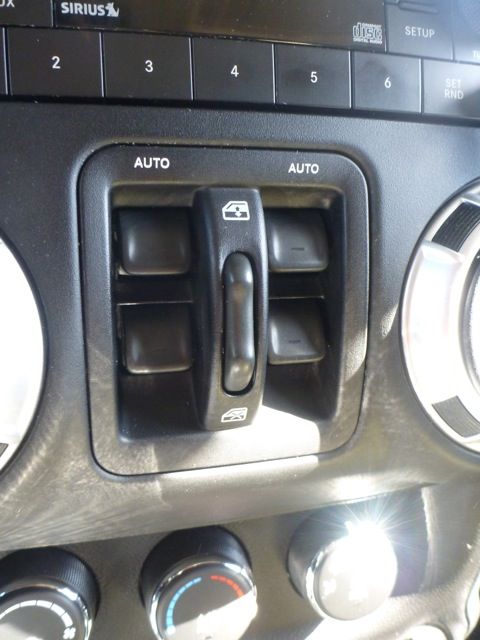
About 40,000 miles in, the back lights on my power window switches started to burn-out. Being OCD, I could not stand the fact that my switches were not uniform in the dark. By the second burn-out, I decided I had enough! And the madness would not continue! I decided to crack open the Power Window Switch Module, and replace the incandescent lamps with some long lasting LEDs. Here’s a write-up on how I did it.
I decided to use Cool White LEDs. There are actually blue filters built into the switches to “color correct” the stock incandescent lamps to the factory green you see.
Yellow (Warm Light) + Blue (Filter) = Green
So the Cool White LEDs I chose now give the switches a nice blue light. If you wish to keep the stock green light, I would suggest buying the Warm White LEDs or even the Yellow LEDs to impersonate the warm light you would get from the stock incandescent lamps.
If for some reason you completely mess up and break the circuit board, here's the Part Number (68057595AC) for the Switch Module. It'll run you about $55-$75 online.
What you need:
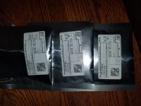
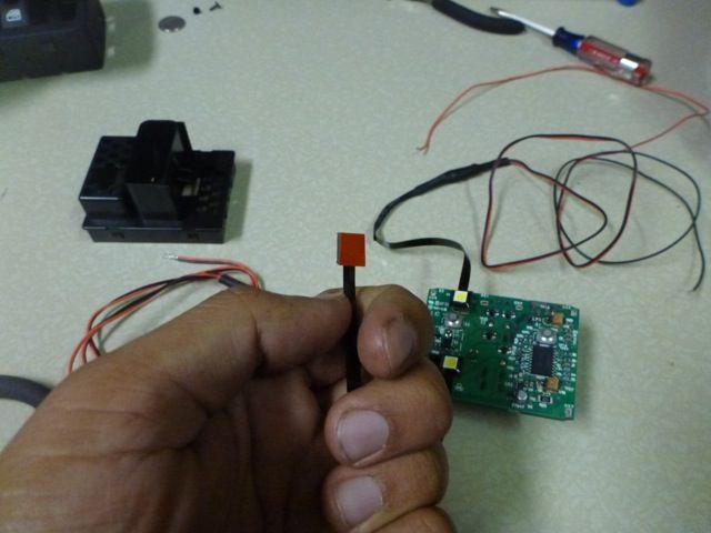
(4) Surface Mount LEDs from Oznium
(6-12”) ¼” Corrugated Tubing
(1) Spade Connector
(1) T-Tap Connector
18 Gauge Wire
Small ZipTies
Heat Shrink
Soldering Iron
Solder
Solder Wick
Small Flat Head Screwdriver/Pry Tool
Small Wire Cutters
Wire Stripper
Crimper
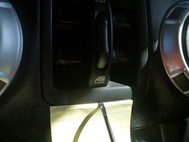
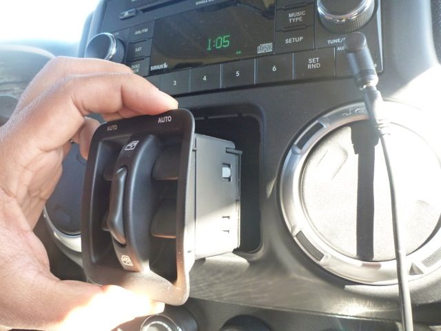
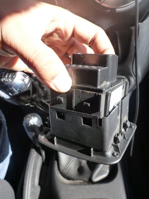
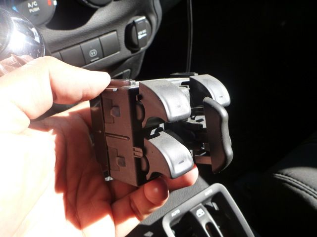
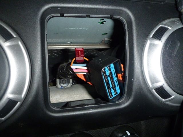
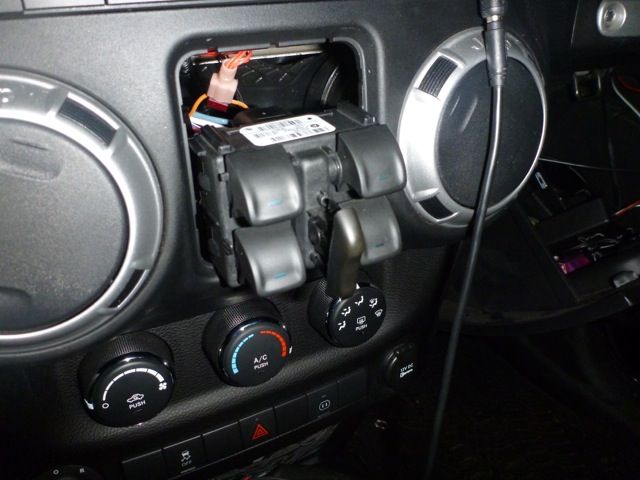
1. With one hand, pinch the Window Lock Switch with your thumb and index finger, and pull up and out on the Switch Module. This will make a bigger gap for the screwdriver blade to fit at the bottom of the Switch Module Front Cover. While pinching the window lock switch, simultaneously pry the bottom of the Switch Module Front Cover with a small flat head screwdriver until the Switch Module pops out. I used a small piece of paper just to protect the dash from some minor scratches.
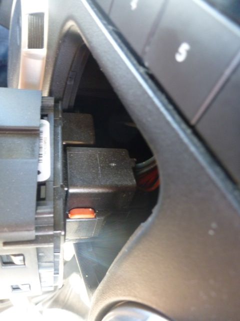
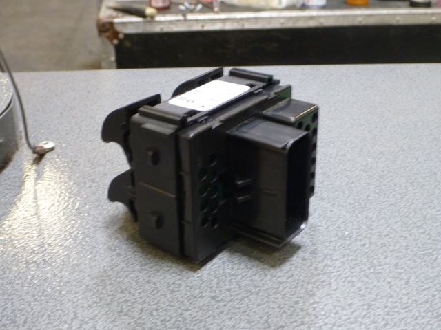
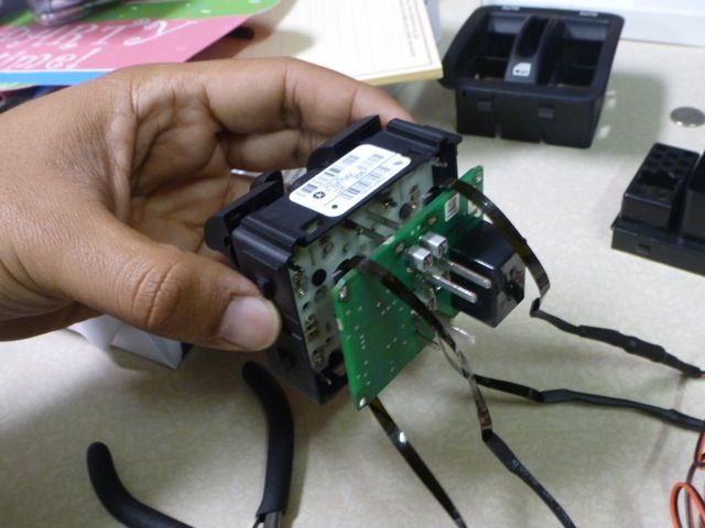
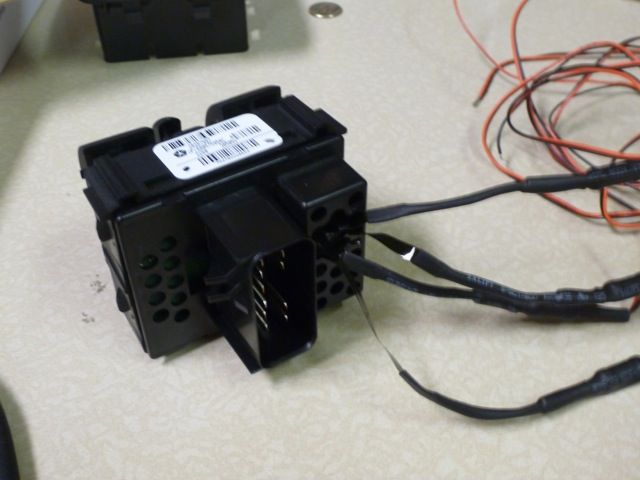
2. On the back of the Switch Module is a red tab. Pull the red tab up, and squeeze the release tab to free the Switch Module from the wire harness.
3. There are four tabs (two on each side) attaching the Switch Module Front Cover to the Switch Module itself. Use a small flat head screwdriver to pry each tab of the Front Cover off the Switch Module.
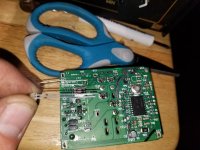
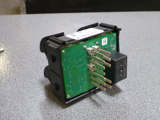
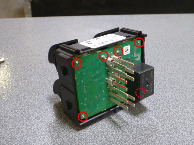
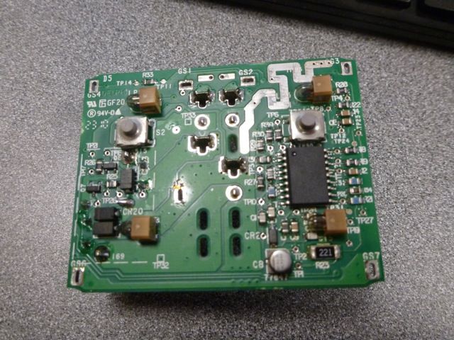
4. There are an additional four tabs (two on each side) that keep the Back Cover of the Switch Module attached to the Switch Module itself. Just like with the Front Cover, use a small flat head screwdriver to pry each tab of the Back Cover off the Switch Module. With the Back Cover off, you can now see the “Pin Side” of the Switch Module circuit board.
5. The circuit board is attached to the Switch plate by 7 soldered anchor points. Using a soldering iron, desolder these points to free the circuit board from the Switch plate. Some solder wick will be helpful to help pull up excess solder during this process.
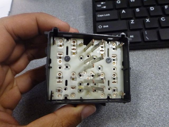
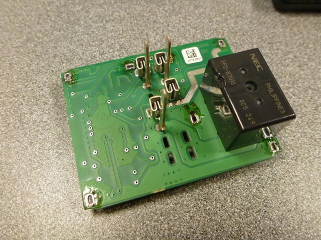
6. With all 7 anchor points desoldered, you can now carefully separate the circuit board from the Switch plate. This may take some wiggling.
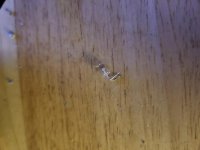
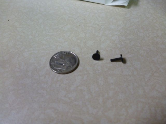
7. Be careful not to lose the 2 very small “push pins” on the Switch plate. These easily fall out, and I actually lost one. Had to retrace my steps to find. As you can see, they’re smaller than a dime. I put these aside when working on the Switch Module. If you loose these pins, you won’t be able to auto roll down your front windows with a single click.

8. Flip the circuit board over, and now you can easily view the 4 incandescent lamps that backlight your Power Window Switches. I decided to “cheat” here a little bit, and not actually replace these lamps, but mask them. The Surface Mount LEDs conveniently have an adhesive back. Peel back the red backing, and stick the LED directly on top of the incandescent lamp. Or if you wish, you can remove the stock lamps all together and place the new LEDs in the same location. The switches will still work fine. For fear of messing up the circuit board, I decided to just leave the stock lamps there.
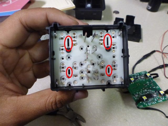
9. Be careful to be as uniform as possible with your placement, as ununiformed placement will cause variations in intensity as the light filters through the switches. Try to line up the center of the LEDs with the open slots on the switch plate. Shown here.
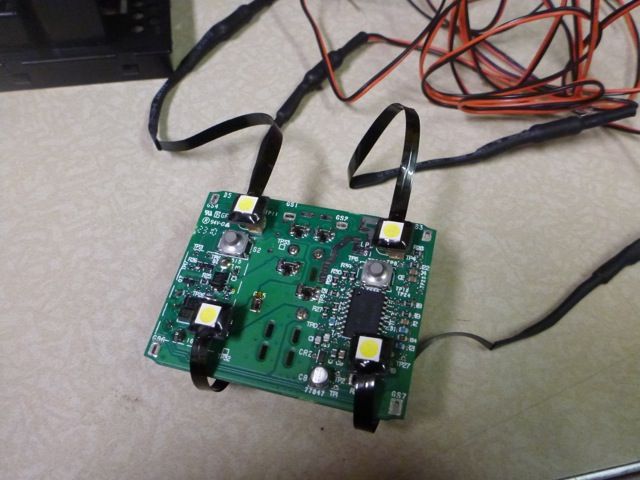
10. With all the LEDs mounted, it’s time to start the reassembly process. Feed the circuit board back on to the Switch plate being careful to make sure all the wire webbing is organized and flat.
11. Once the circuit board is back in place, resolder all the anchor points. You’ll notice that circuit board will sit a few millimeters higher than before due to the LEDs, but they will fit fine. Just be sure you can still resolder all 7 points.
12. Use small wire cutters to make a bigger hole in the Back Cover to feed the LED wire leads through.
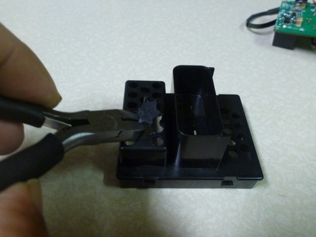

13. Once the wire leads are fed through the hole, reattach the Back Cover to the Switch Module until it clicks into place. Again be careful to make sure all wire webbing is organized and flat before snapping the Back Cover back on.
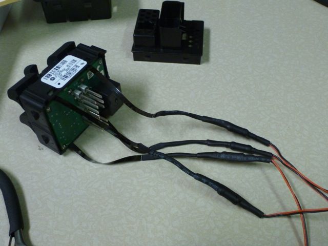
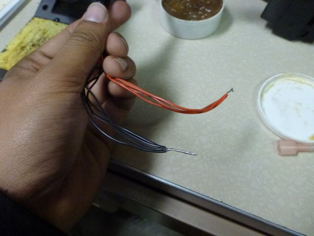
14. Now you can begin to make your LED wire harness. The LEDs will come with about 36” of end wire. I decided to cut this down to 8-12”. Split the Positive from the Negative leads, and strip all ends. Splice all the Positive leads together. Then splice all the Negative leads together.
15. I used ZipTies and Corrugated Tubing to clean things up a bit.
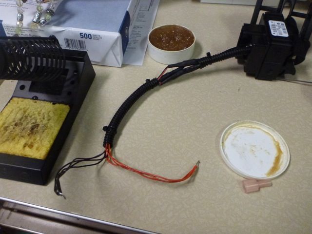
16. Crimp a Spade Connector to the Positive lead.
17. Splice a few feet of 18 gauge wire to the Negative end. Make sure to have enough wire to reach a Grounding point of your choice. I used the Grounding point on the passenger’s side footwell.
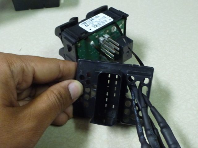
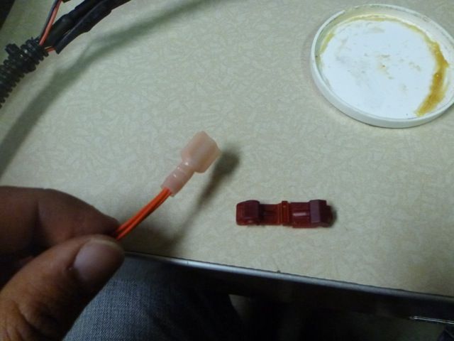
18. On the wire harness, add a T-Tap Connector to the Orange wire with a Gray stripe. There are two Orange with Gray wires on the harness, tap into the smaller gauge wire. If you’re looking at the connectors of the wire harness, it’ll be the second pin down from the top on the passenger’s side. Again, Orange wire with Gray stripe.
19. Connect the Spade Connector to the T-Tap, and hook-up your Negative to a Grounding point.
20. Reconnect the Switch Module and the wire harness, and lock the red tab back down.
21. Snap the Switch Module Front Cover back on to the Switch Module.
22. Snap the entire Switch Module assembly back into the stock location.
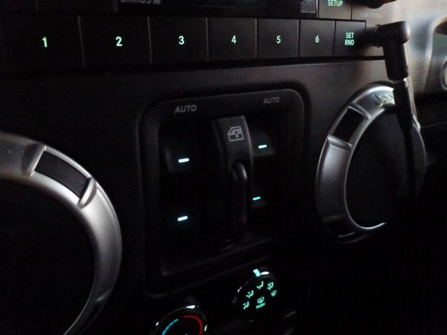
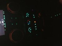
And there you have it! Your Power Window Switches are now backlit with long lasting LEDs with the color of your choice. And best of all, because you tap'd into the wire harness, they will turn on/off and dim with the rest of your dash lights!
:beer:
It's possible to replace the leds on the circuit board or you can use the surface mount leds to place on top of the existing burnt out ones or you can just buy a new switch module. I used the surface mount leds and worked like a charm.Hello, I'm new to this forum, and I have a question: the power window switches light is burn-out. Do I need to replace the switch or I can just replace the bulb/led?
Thanks,
D
It's possible to replace the leds on the circuit board or you can use the surface mount leds to place on top of the existing burnt out ones or you can just buy a new switch module. I used the surface mount leds and worked like a charm.
Sent from my SAMSUNG-SM-G930A using WAYALIFE mobile app