A little over 5 years ago, Cindy and I had Moby's suspension upgraded from the Gen 1 EVO Coil Over kit to a full blown DTD or Double Throw Down system. In other words, we got an all new EVO Lever frame and cantilever arms installed to accommodate the bypass shocks and while we were at it, we updated all the heims but kept our original 8" rear coil overs as they could still be used. Since that time, we've racked up about 100,000 miles on the EVO Lever and aside from routine servicing of the coil overs, all the other components such as the bushings and heims have all remained the same.
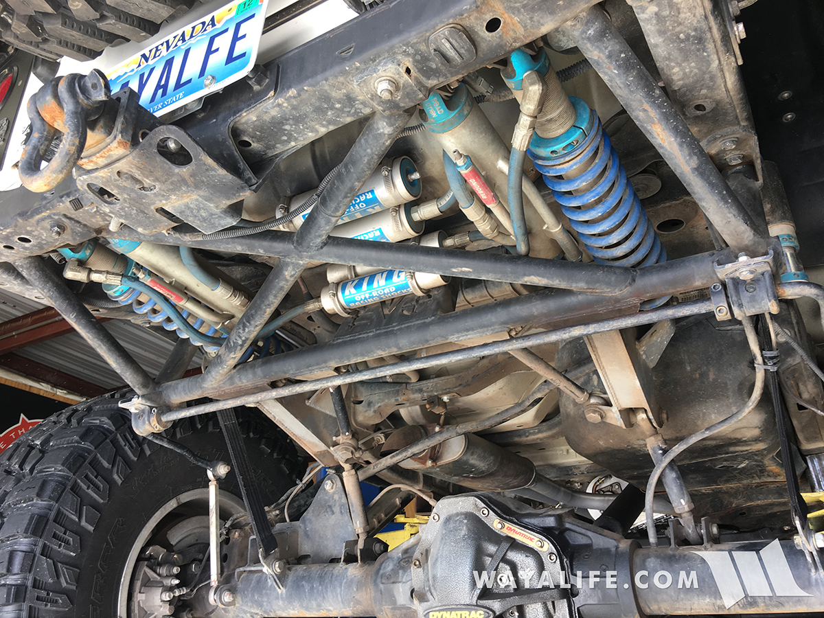
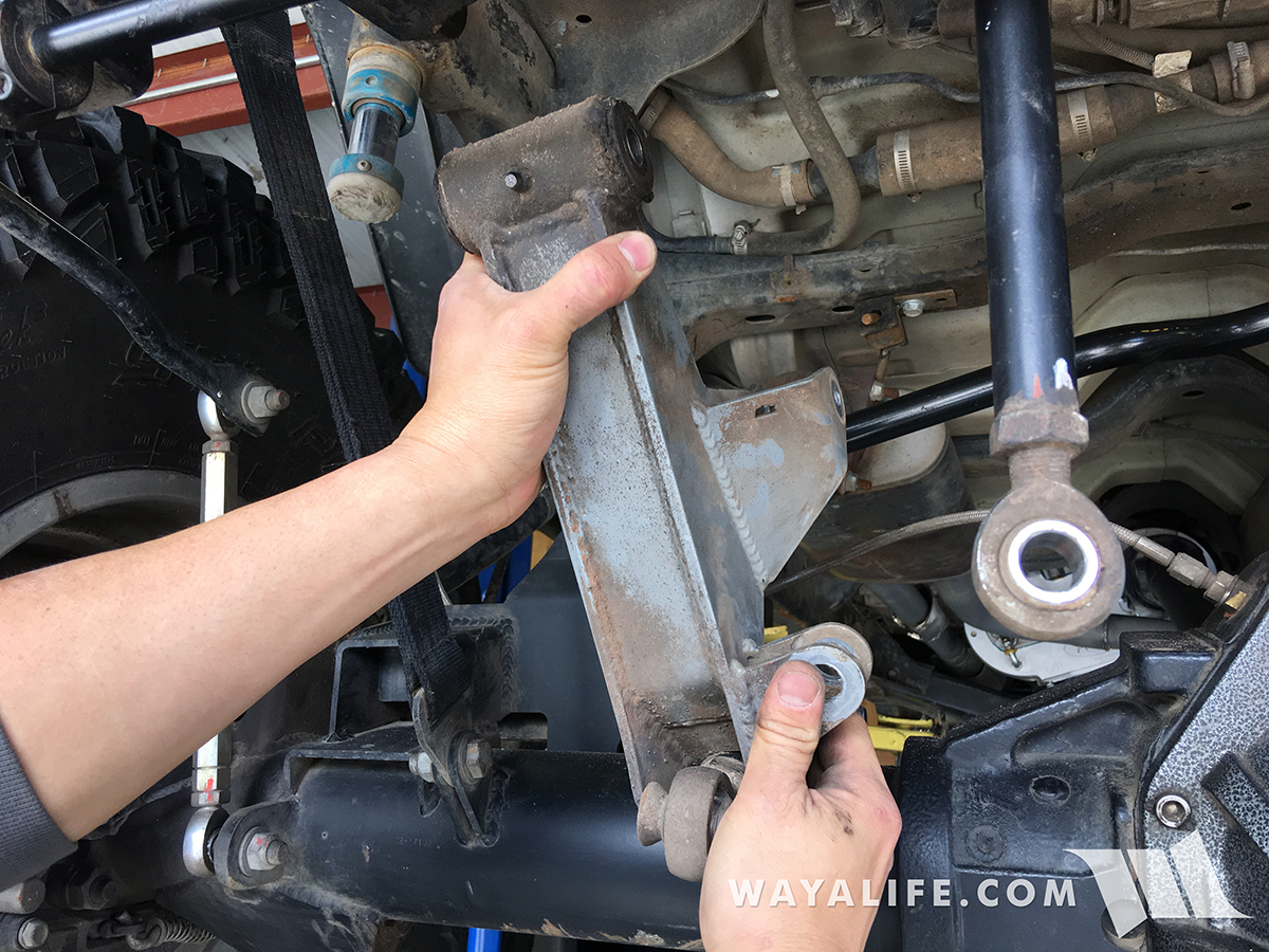
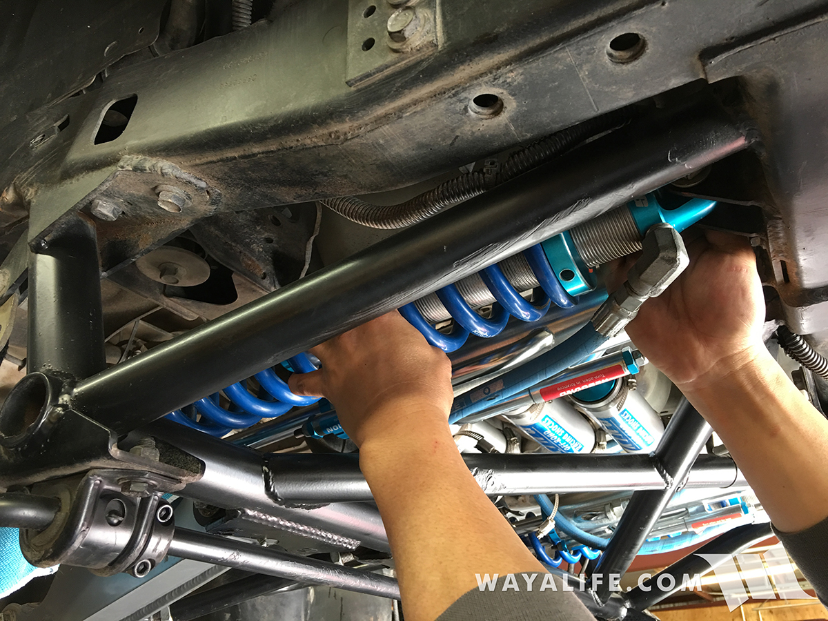
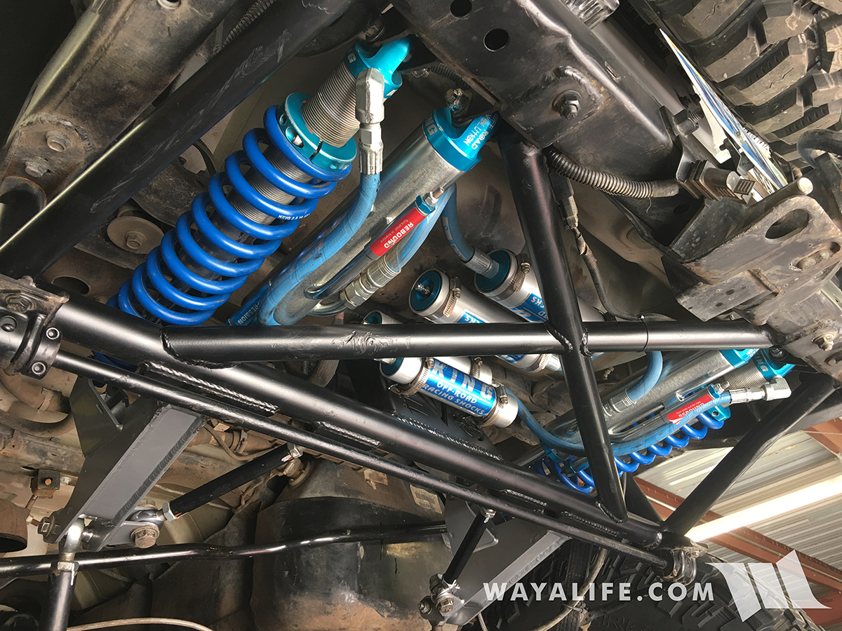
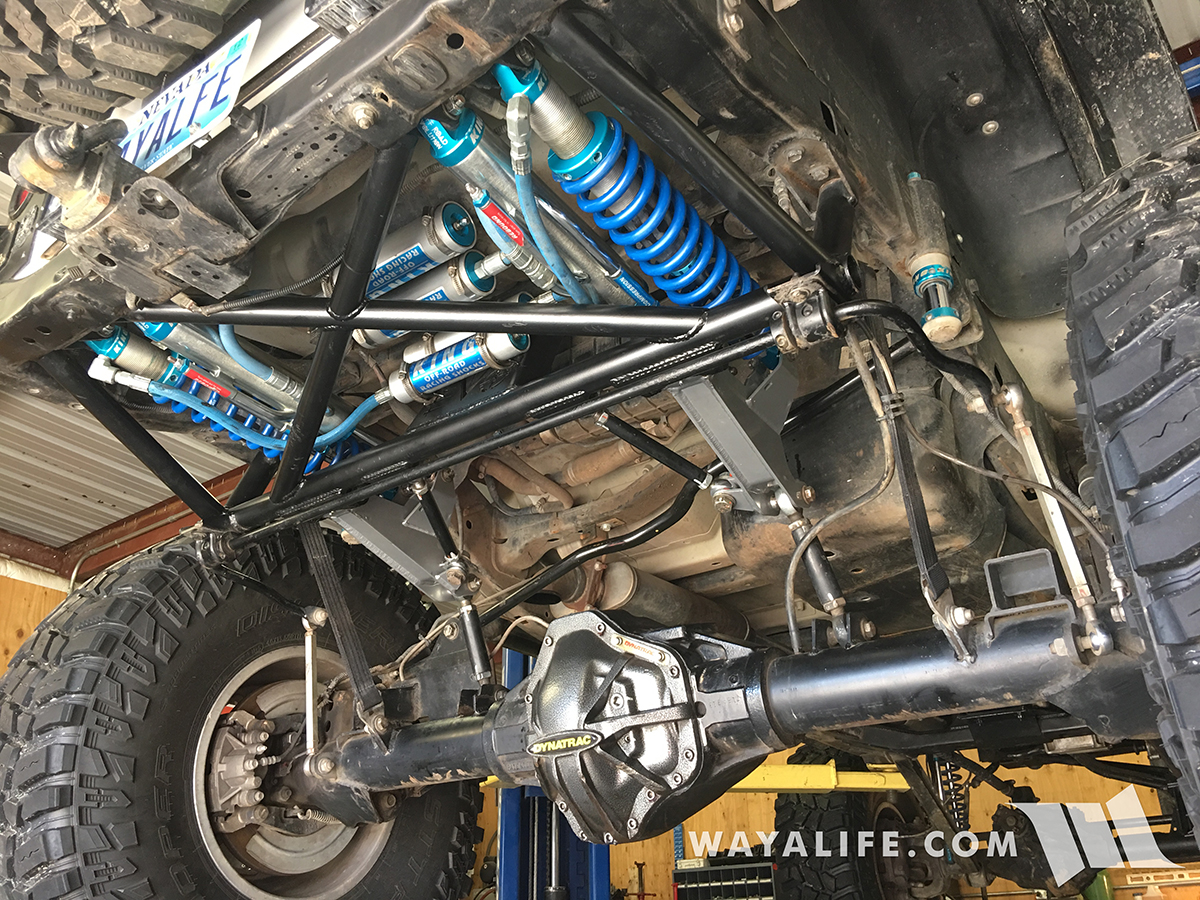
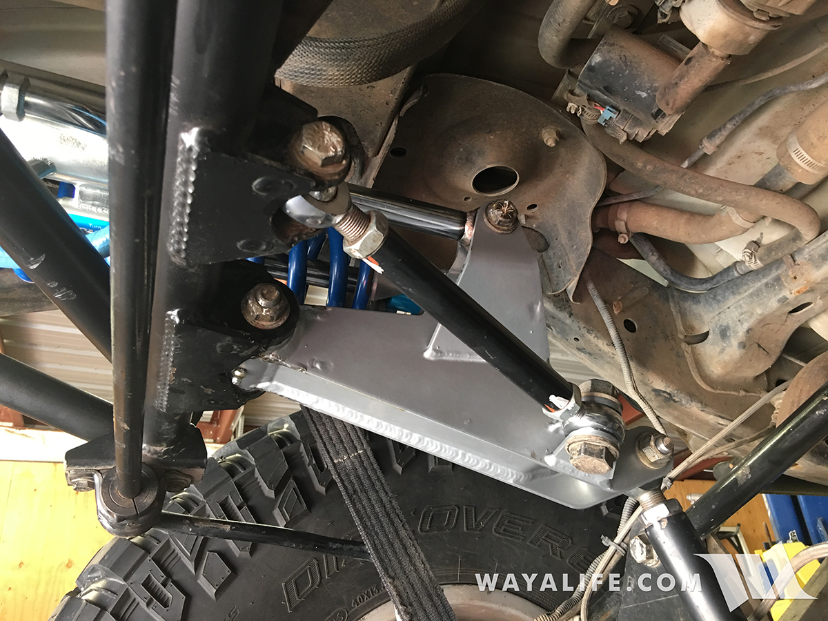
For a while now, I've known that something was starting to get a bit off on the EVO Lever but I just was too busy wheeling and working on other Jeeps to take time out and address it. The first sign of something being wrong was an obnoxious squeaking that we'd get from time to time but it would always end up going away and that made it hard for me to keep looking for it. Recently, I started to hear an occasional but distinct clunk under acceleration that's when I knew I needed to give things a harder look. And, when I did, I noticed the following. To someone who's unfamiliar with what an EVO Cantilever arm should look like, this passenger side one is leaning and it shouldn't be.
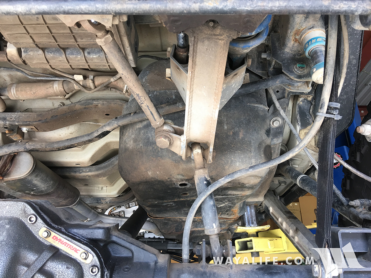
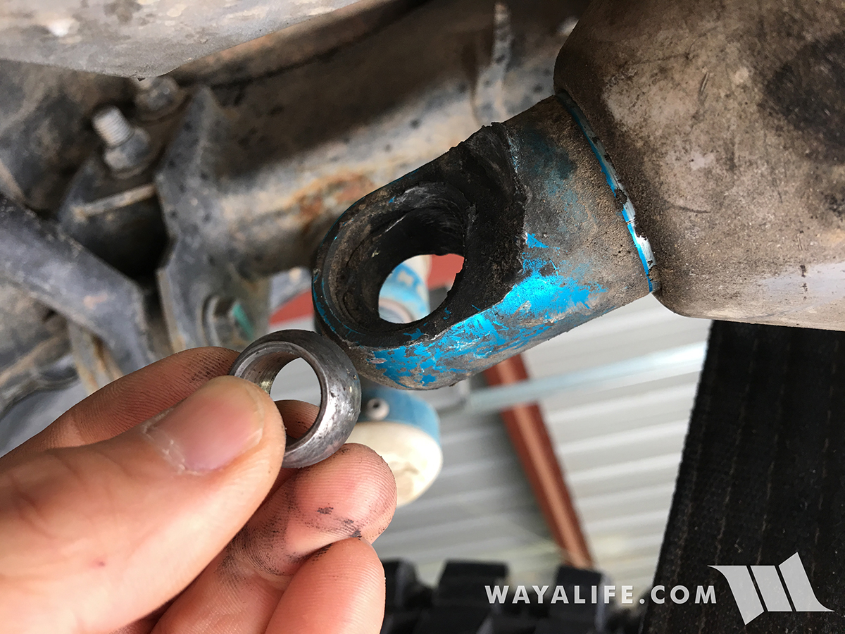
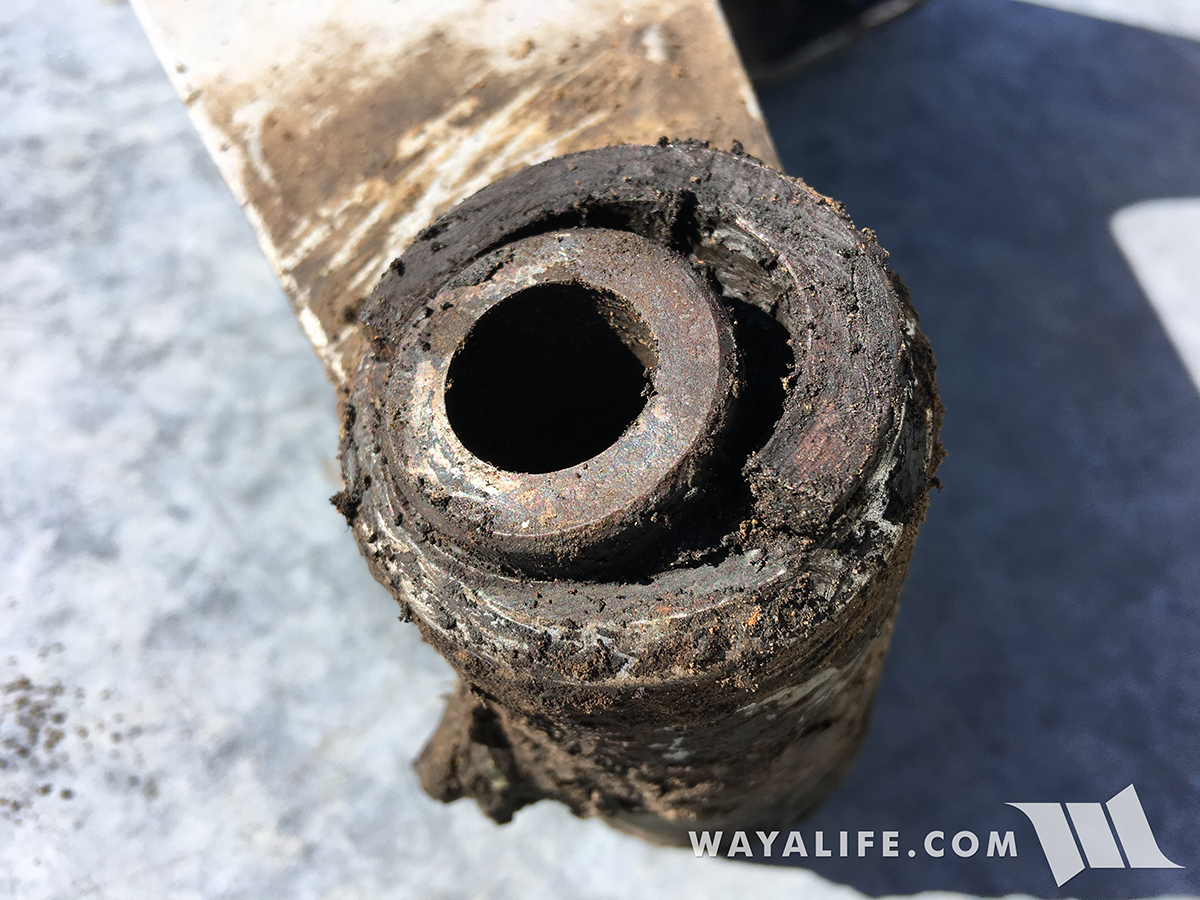
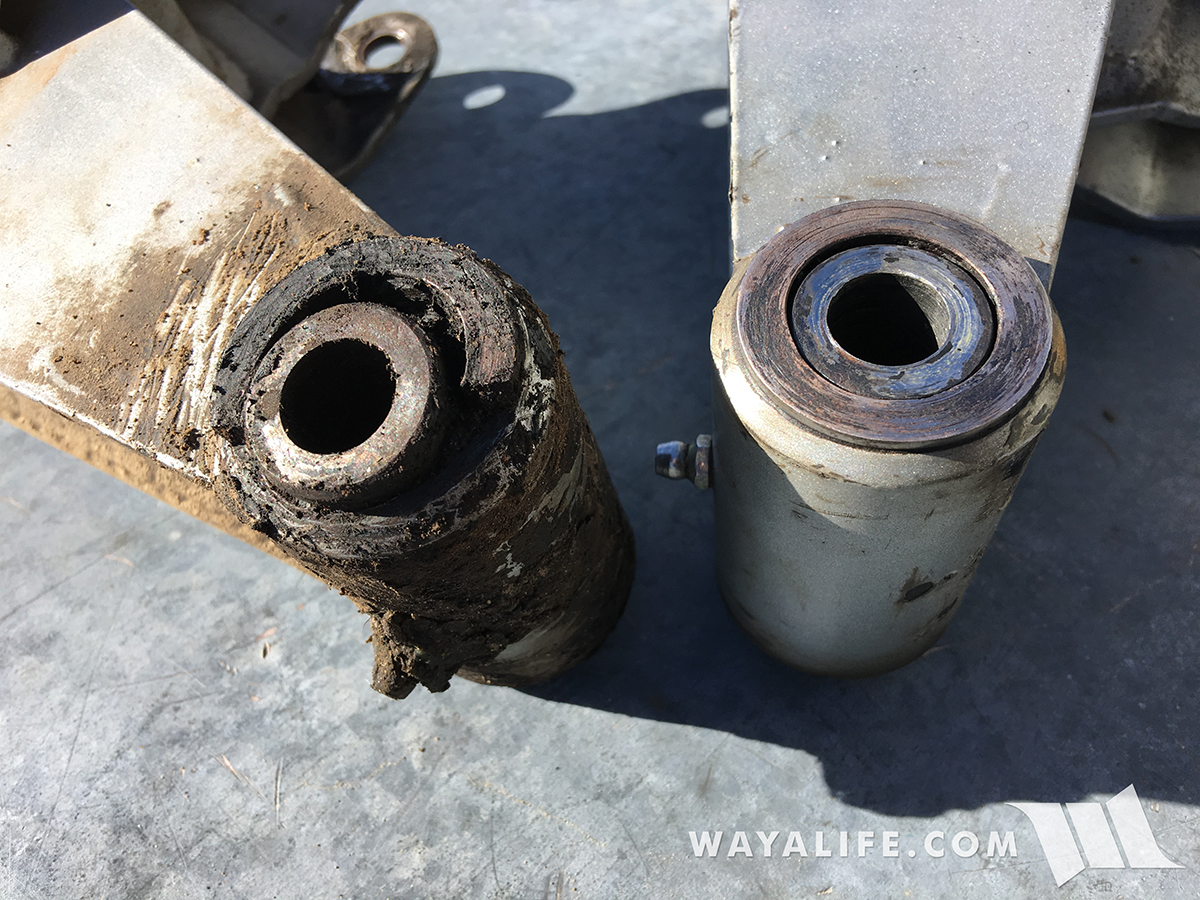
It might might not look like much but for those who know what to look for, you'd know that the cantilever arm bushing here is blown.
Thinking that all we were going to need was a new bushing, we called up Mel to order up a new one but he recommended that it might be better to just replace both cantilever arm. With the amount of miles and abuse we've put them through, it would be the better way to go. Needless to say, that's what we did.
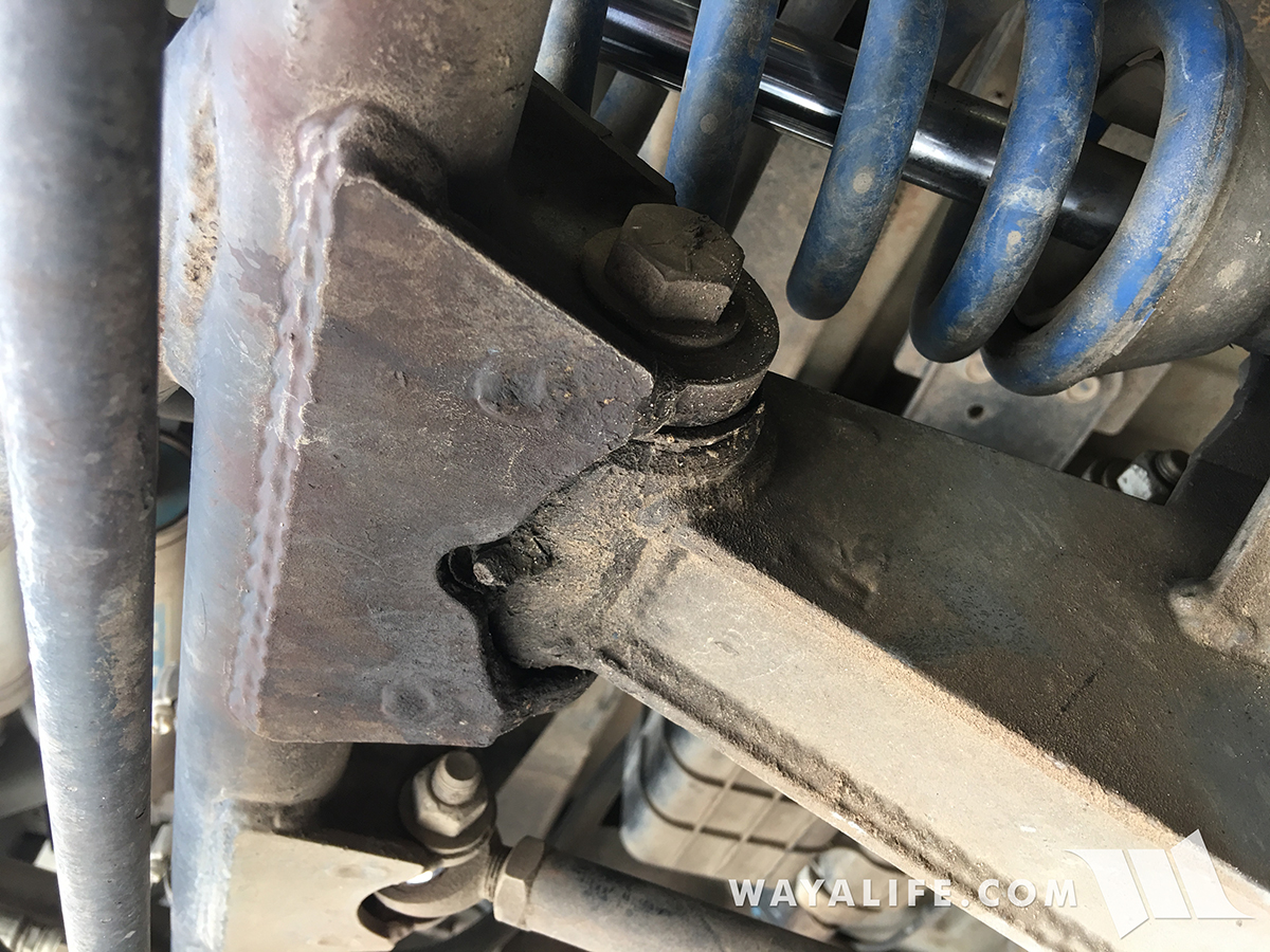
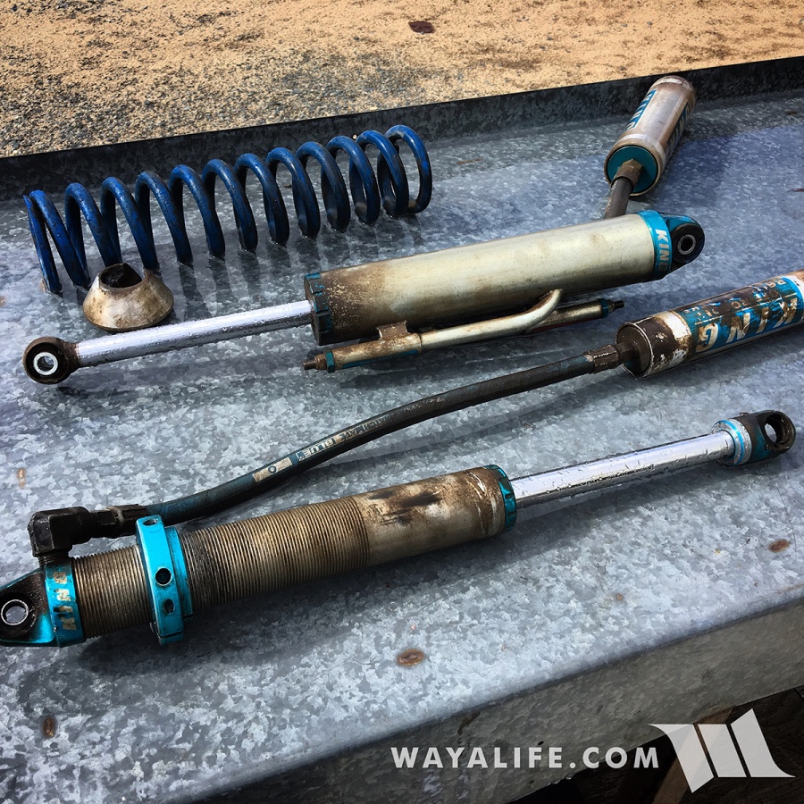
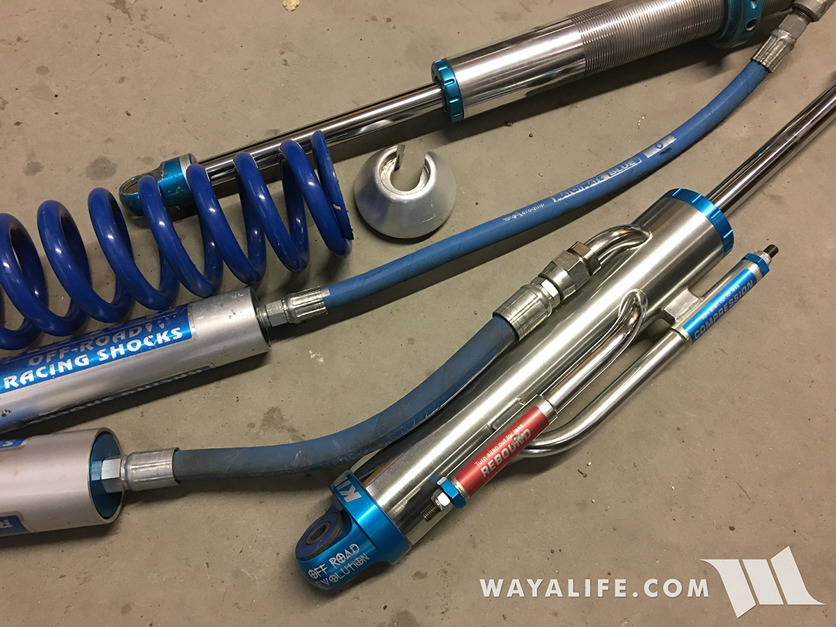
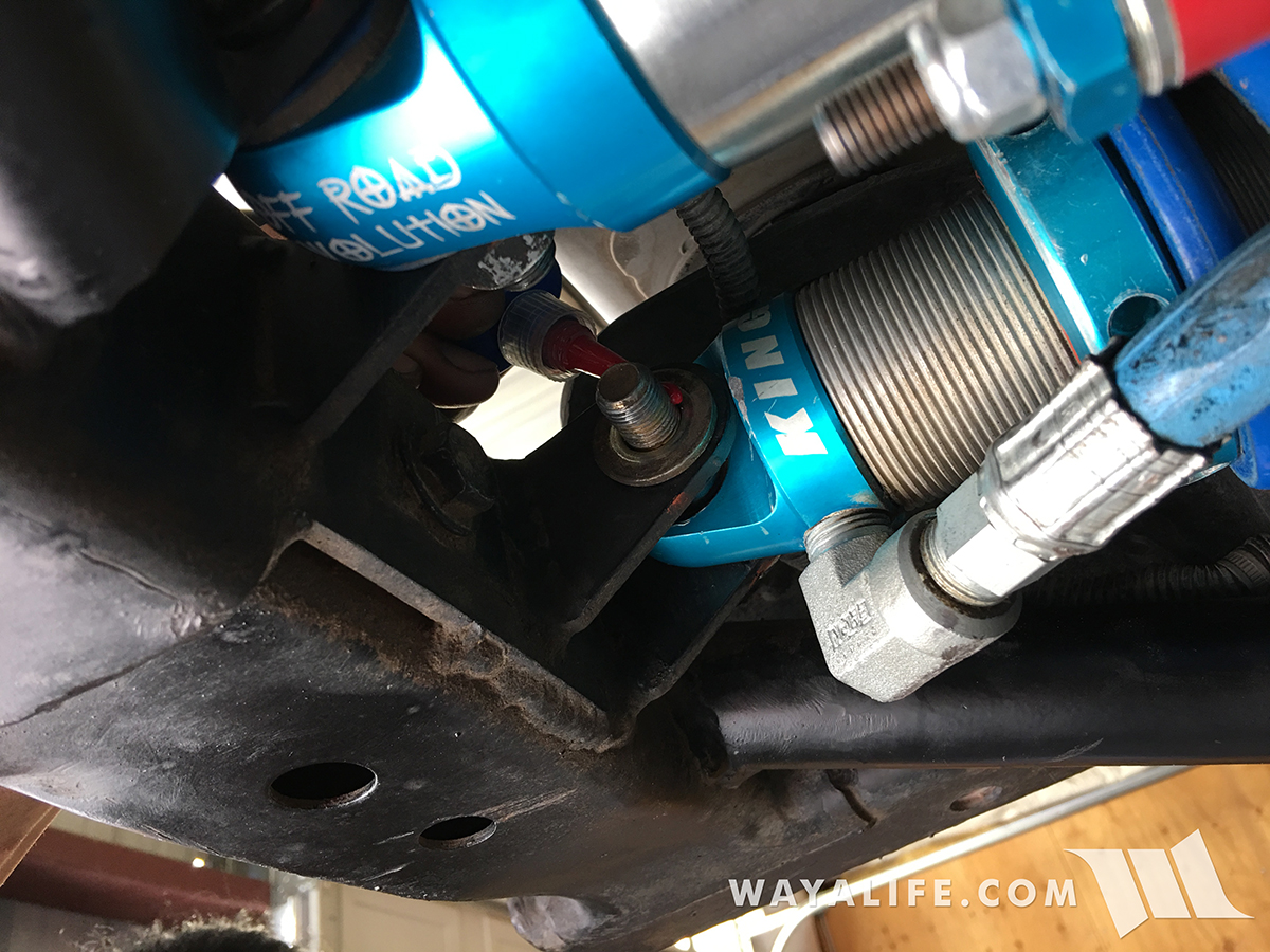
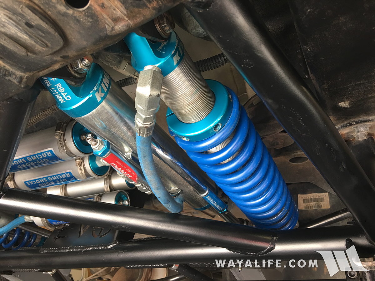
Because of the way the King coil over rod end is situated in the cantilever arm, it was difficult to do a good visual inspection of it and as I started to take things apart, I came across this. Some how, I don't think the spherical bearing is supposed to just fall out like this.
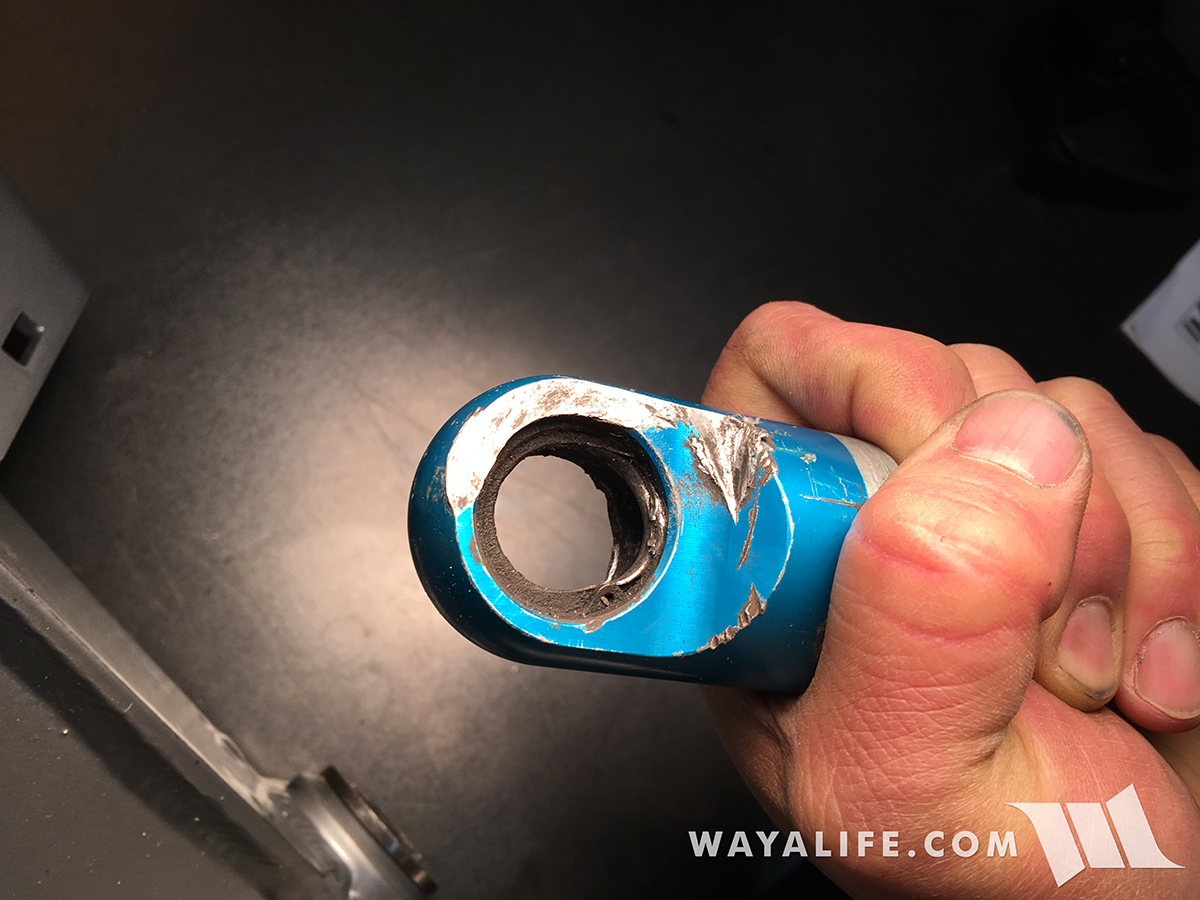
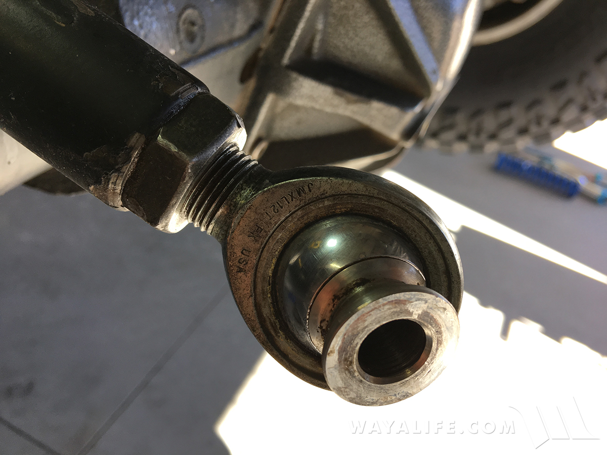
Here's a closer look at the rod end. As you can see, the spherical bearing of the heim had completely wore through it's housing. You can also see where the rod end itself has a grove cut into it from coming into contact with the cantilever arm.
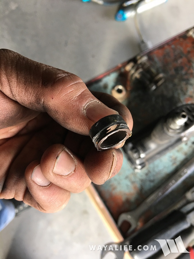
You can also see how the small bearing spacers had dug into the cantilever arms and started to wear through.
Being that our cantilever arm swap just turned into a coil over rebuild as well, I decided to document the whole process and make a write-up out of it. For those of you who own a DTD and work on your own Jeep, I hope this will of some help to you.
What you will Need
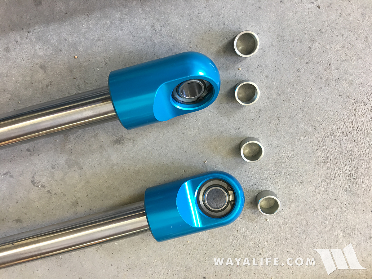
(2)EVO DTD Cantilever Arms w/Bushings installed
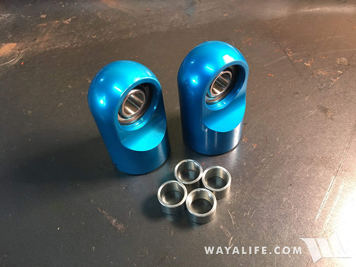
(2) 2.0 PR Rod Ends 7/8 Thread Standard #21002-040
(2) Spherical Bearings 0.5 #B1012
(4) Retaining Rings, INT .500 BRG, 1.000 #CR2201
(4) 2.0 PR Bearing Spacers 1/2 x 1-1/4 #21017-001
• 3/4, 13/16, 7/8, 15/16" Socket & Wrench
• 3/4" Gearwrench
• 3/16" Allen Wrench
• Coil Over T-Handle Adjuster #25308-100 (2.0 & 2.5)
• Ratchet
• Torque Wrench
• Snap Ring Pliers
• Grease Gun
• Red Loc-Tite
• Pry Bar
• 5/16" Driver or Flathead Screwdriver
• Hammer
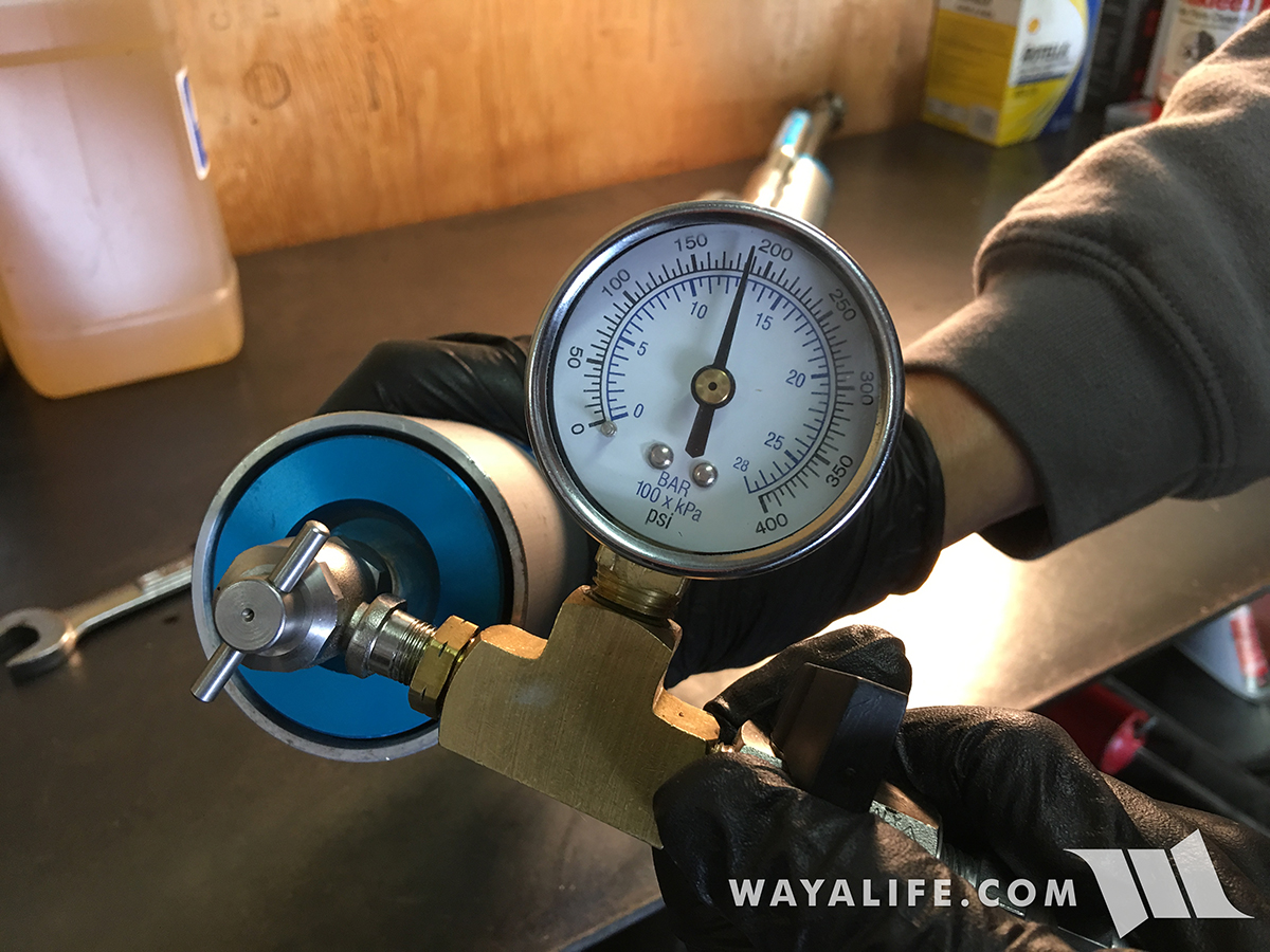
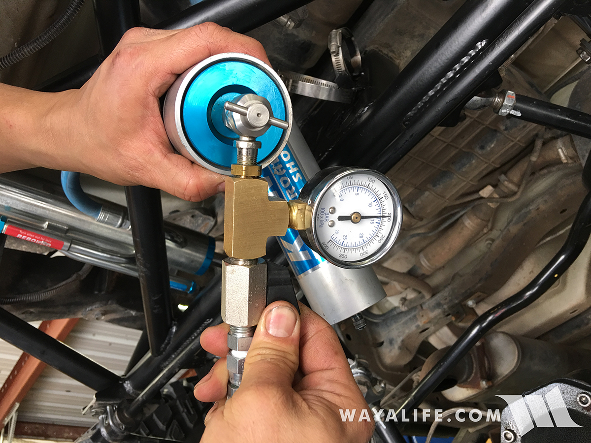
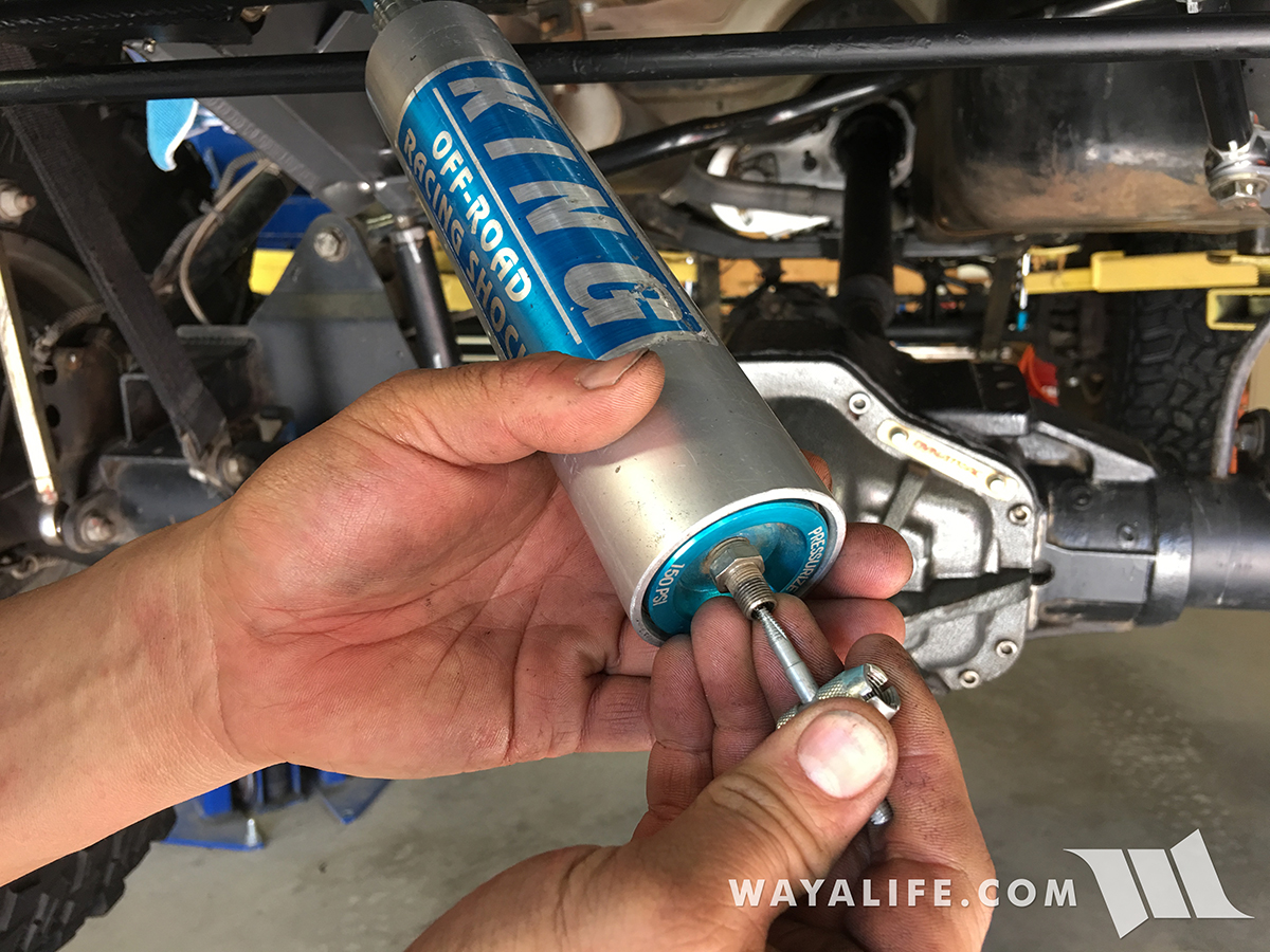
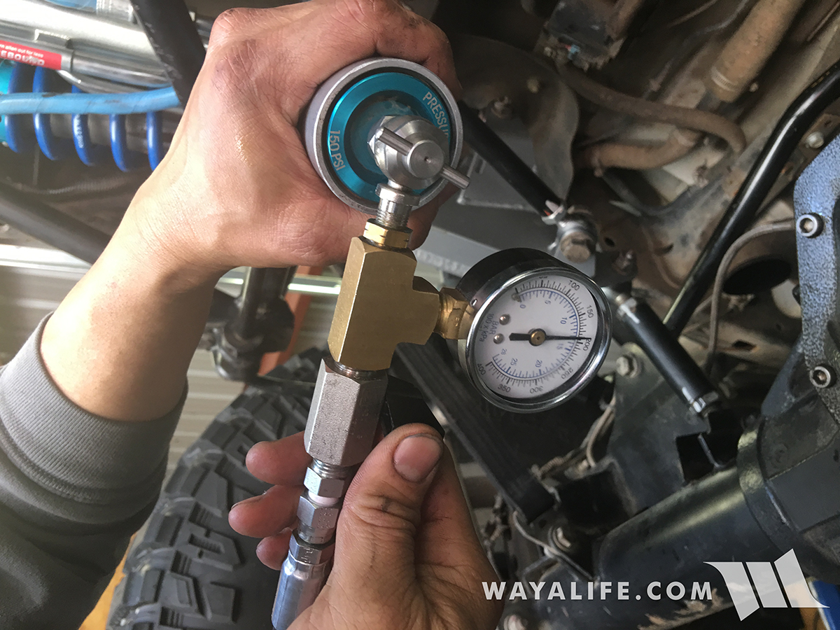
• Nitrogen
• Charging Manifold
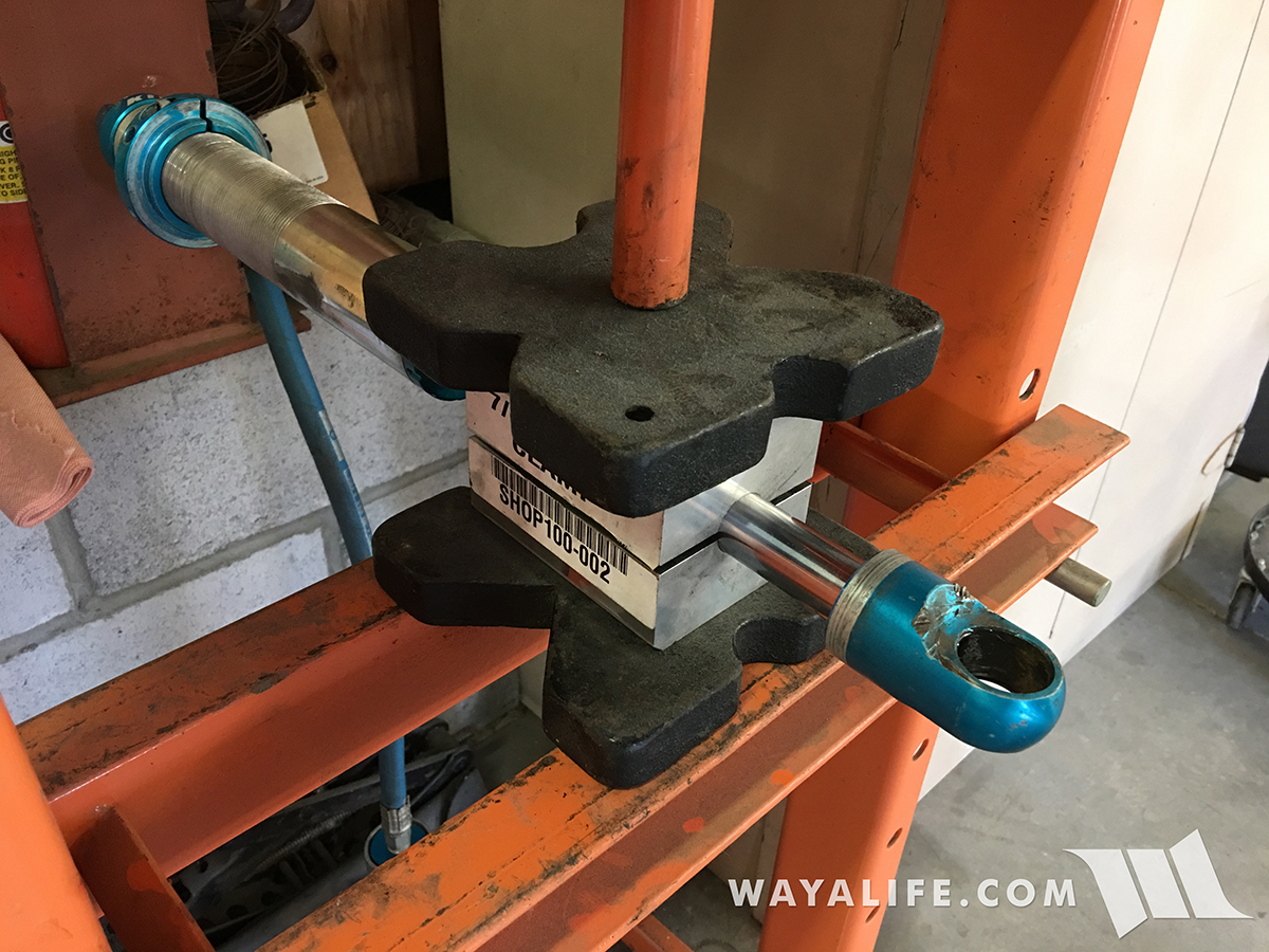
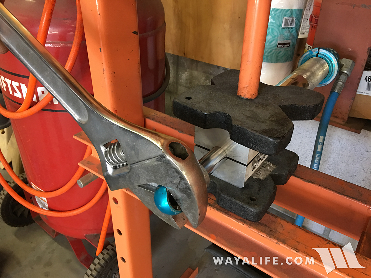
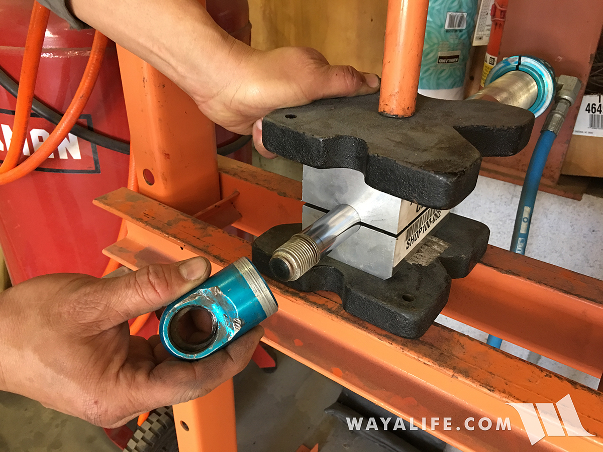
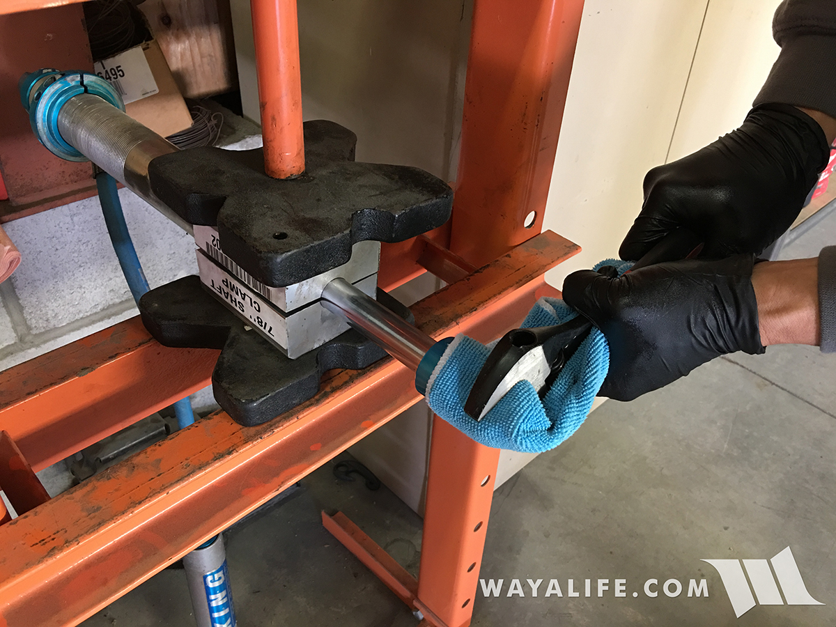
• Cylinder Shaft Soft Jaw Clamp #100-001-(3/4”shaft)
• Shop Press
Instructions
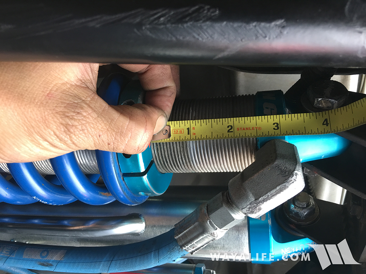
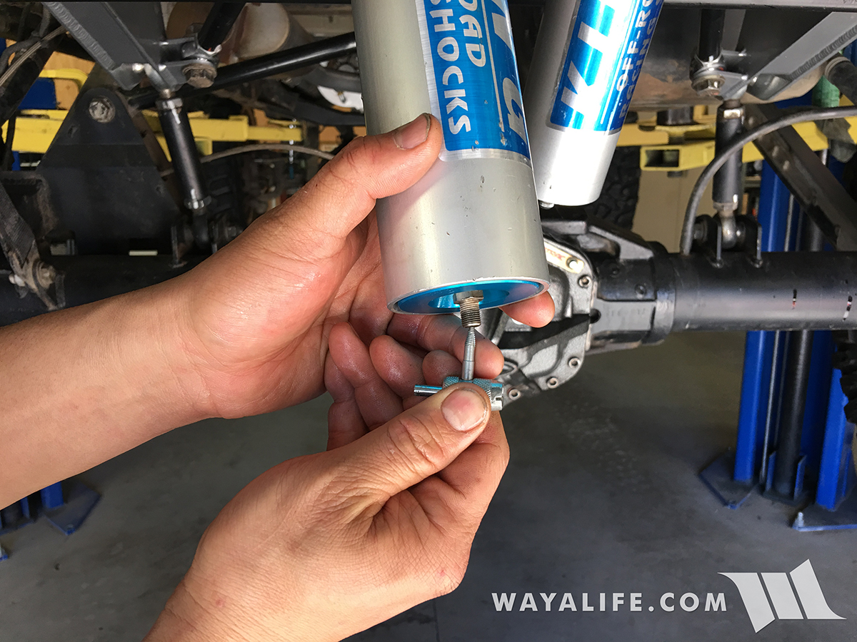
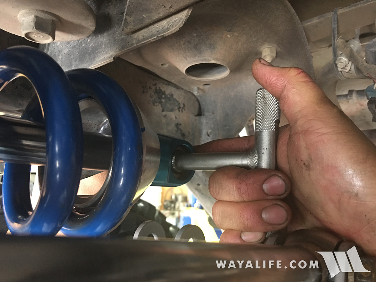
1. After racking up your Jeep so that your rear tires are off the ground, measure the amount of pre-load you have on both your coil overs and make a note of it. Then, loosen the coil adjustment pinch bolt using a 3/16" allen wrench.
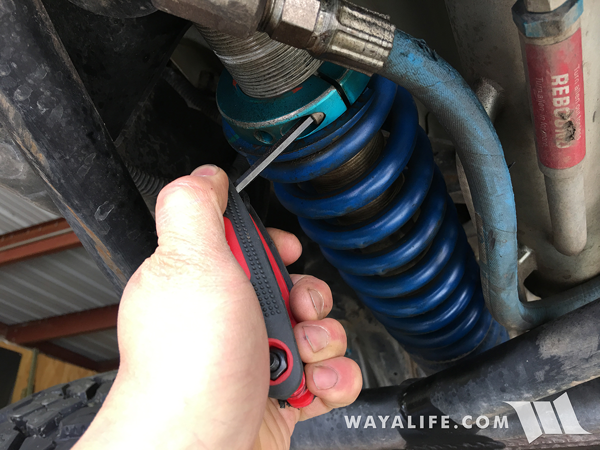
2. Use a coil over T-handle adjuster tool to loosen the coil adjustment nut until there's no longer a load on the coil.
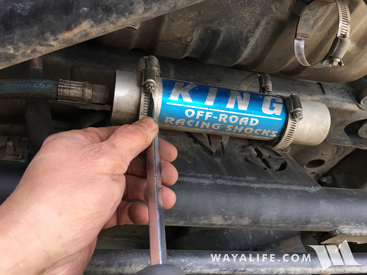
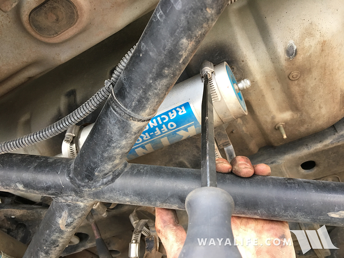
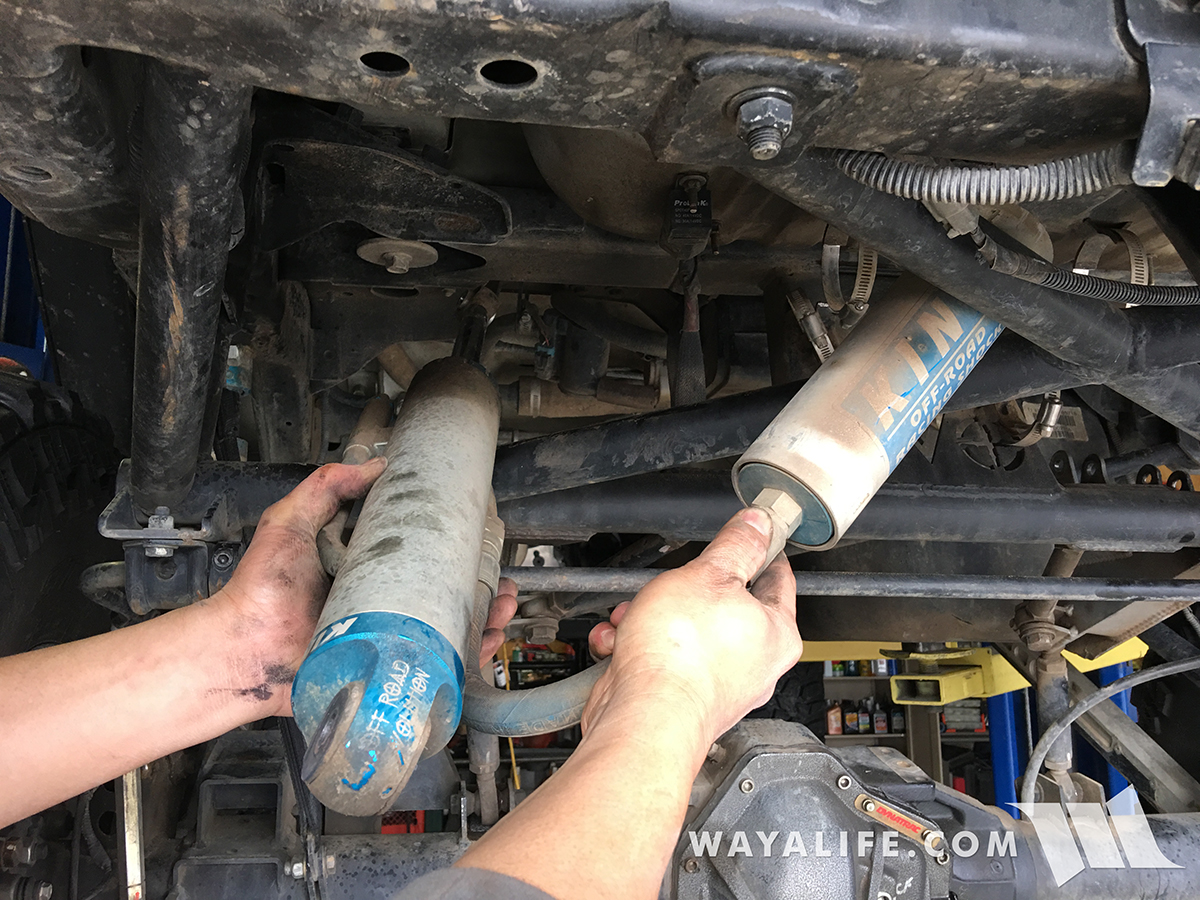
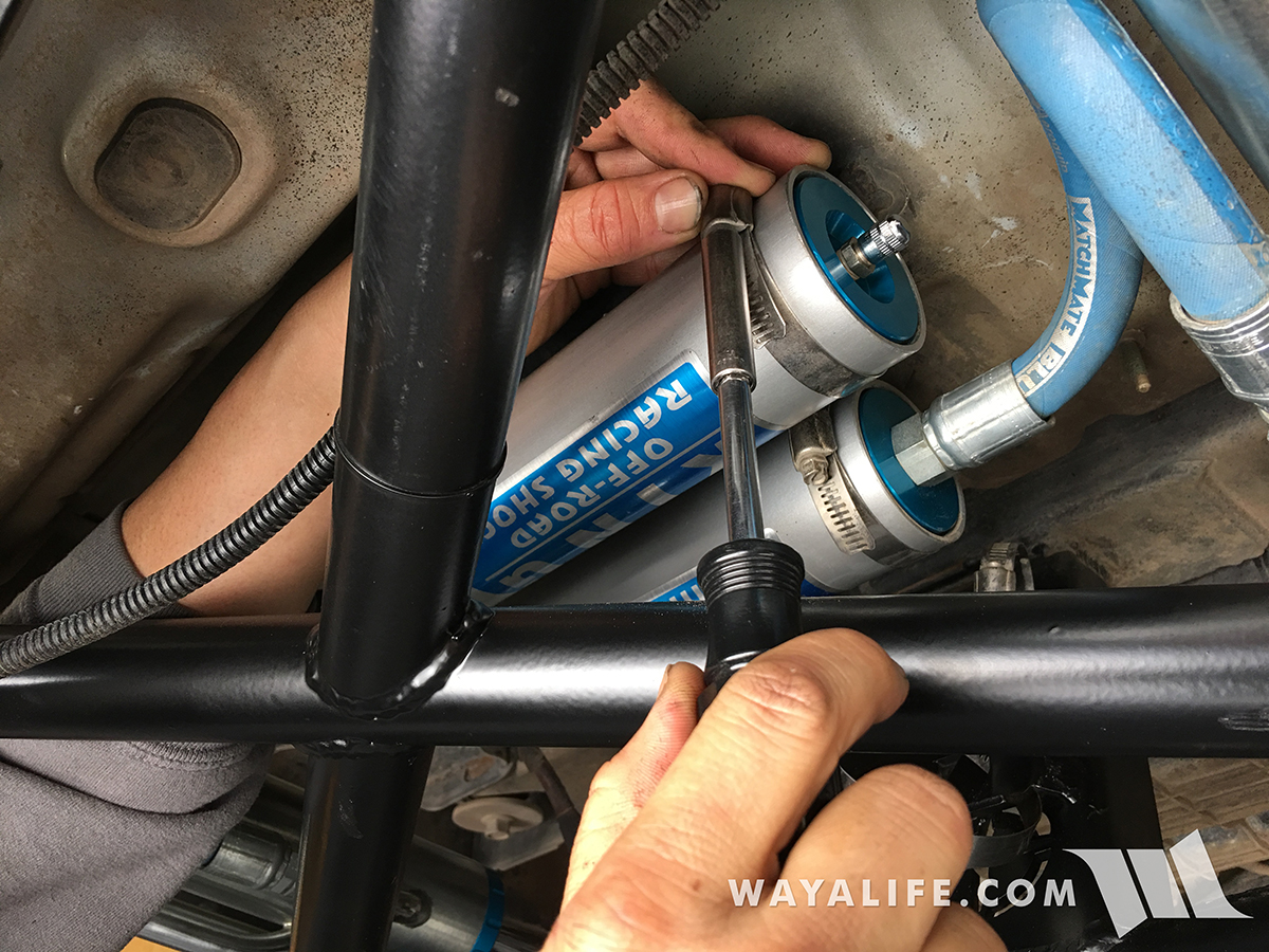
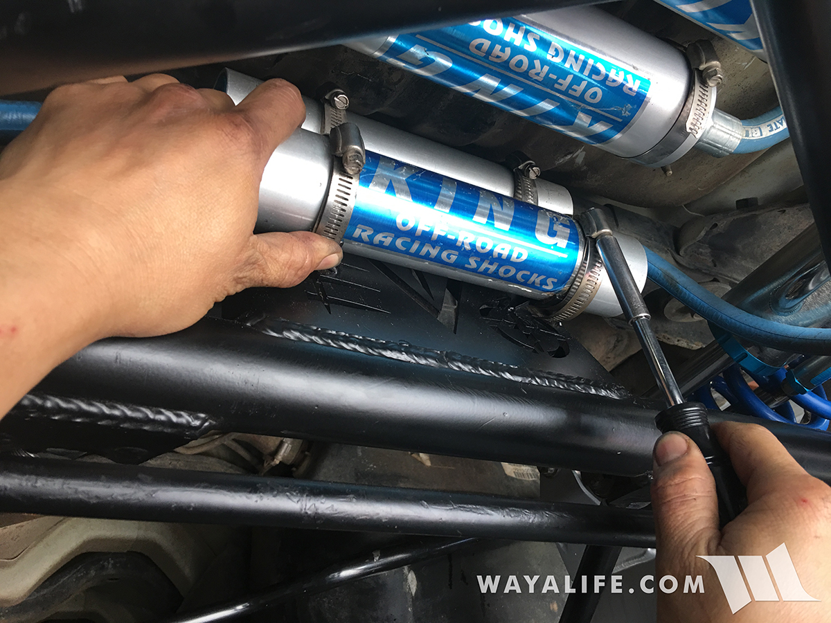
3. Use a flathead screwdriver or 5/16" driver to loosen the hose clamps securing your coil over and bypass shock reservoirs to their mounts on the EVO Lever frame or bottom of your tub.
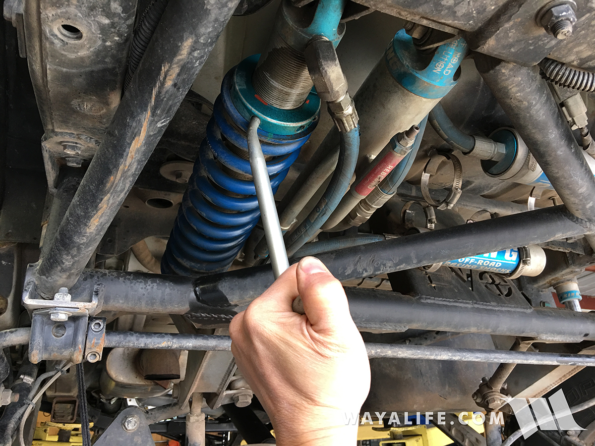
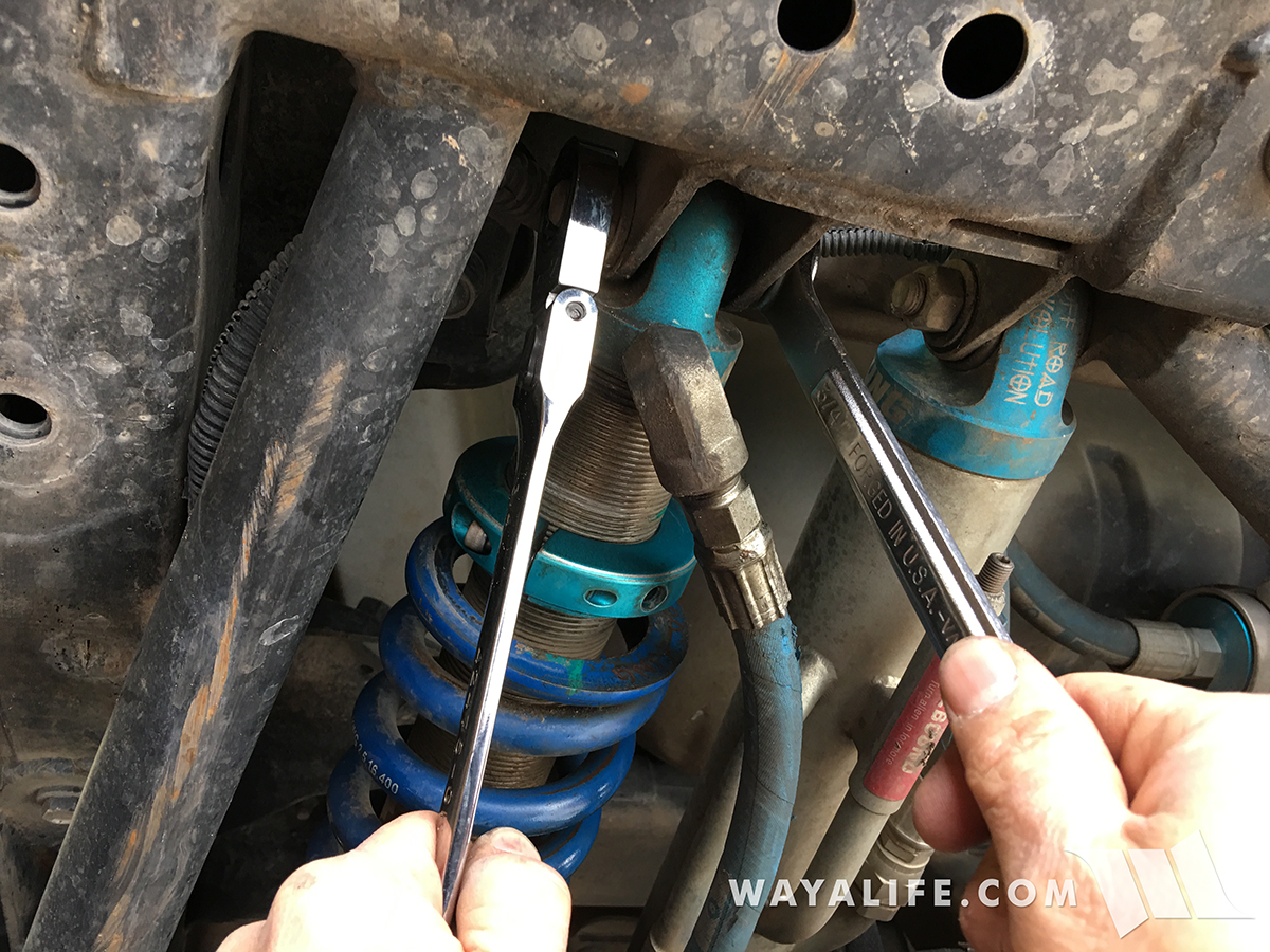
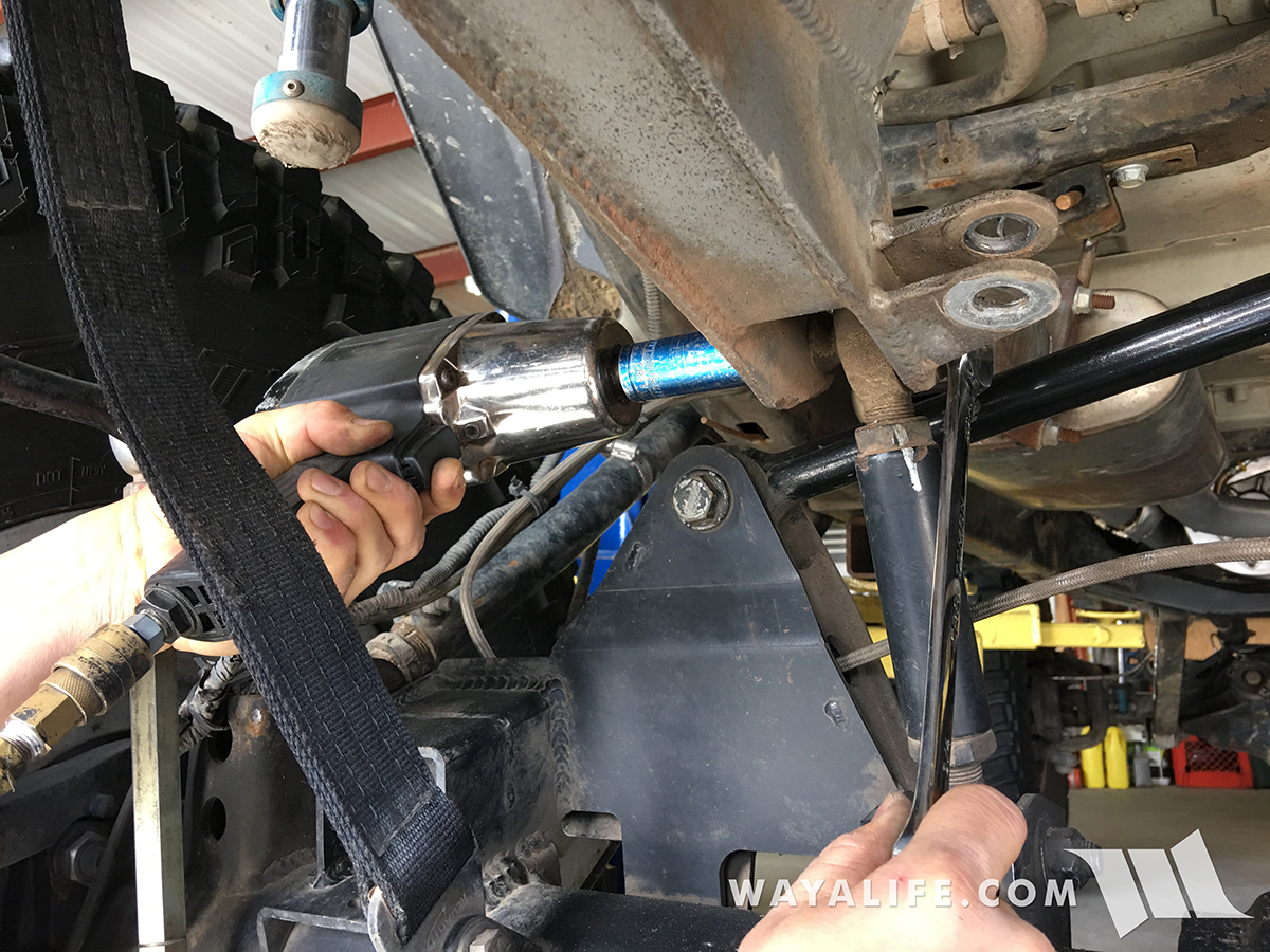
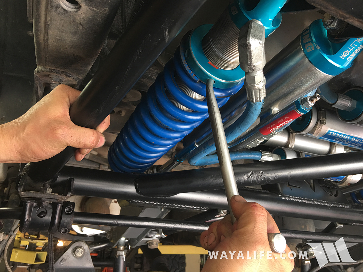
4. Using a 3/4" socket and wrench, remove the bolt, nut and washers securing the coil over to the cantilever arm.
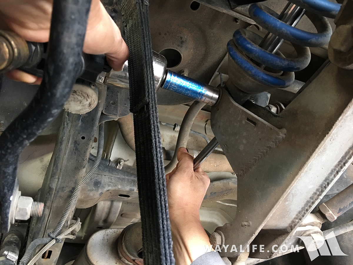
5. You may find it necessary to use a pry bar to free the coil over rod end from the cantilever arm.
6. Using a 3/4" socket and wrench, remove the bolt, nut and washers securing the bypass shock to the cantilever arm.
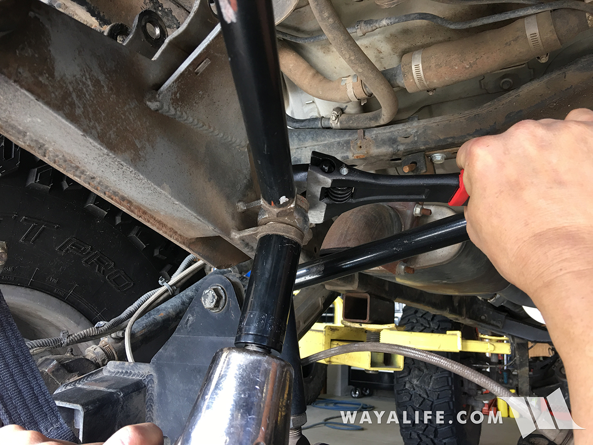
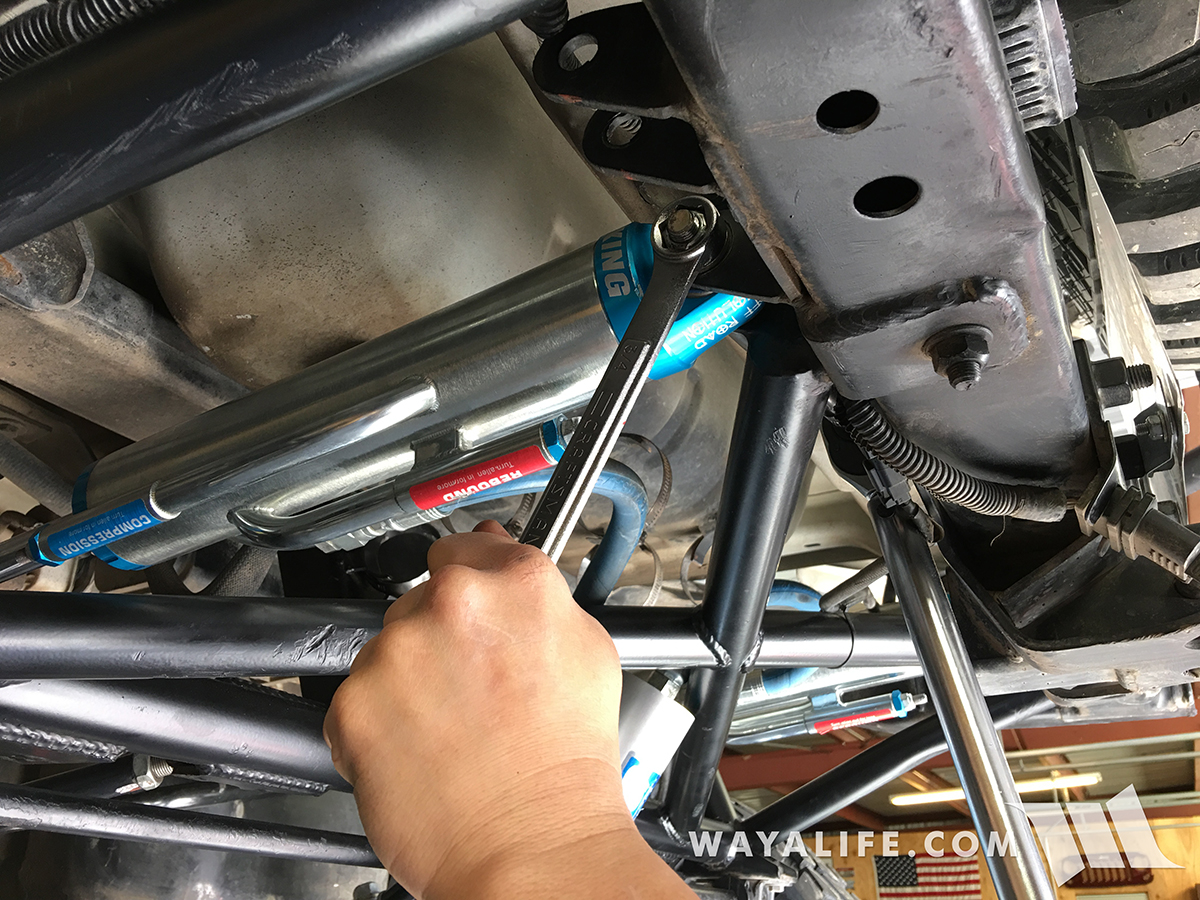
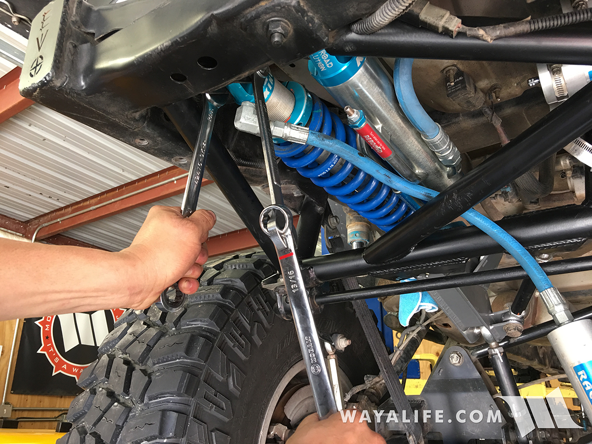
7. You will need to use (2) 3/4" wrenches to remove the bolt, nut and washers securing your bypass shock to the EVO Lever frame as there is no room for a socket. A Gearwrench will help make this job easier.
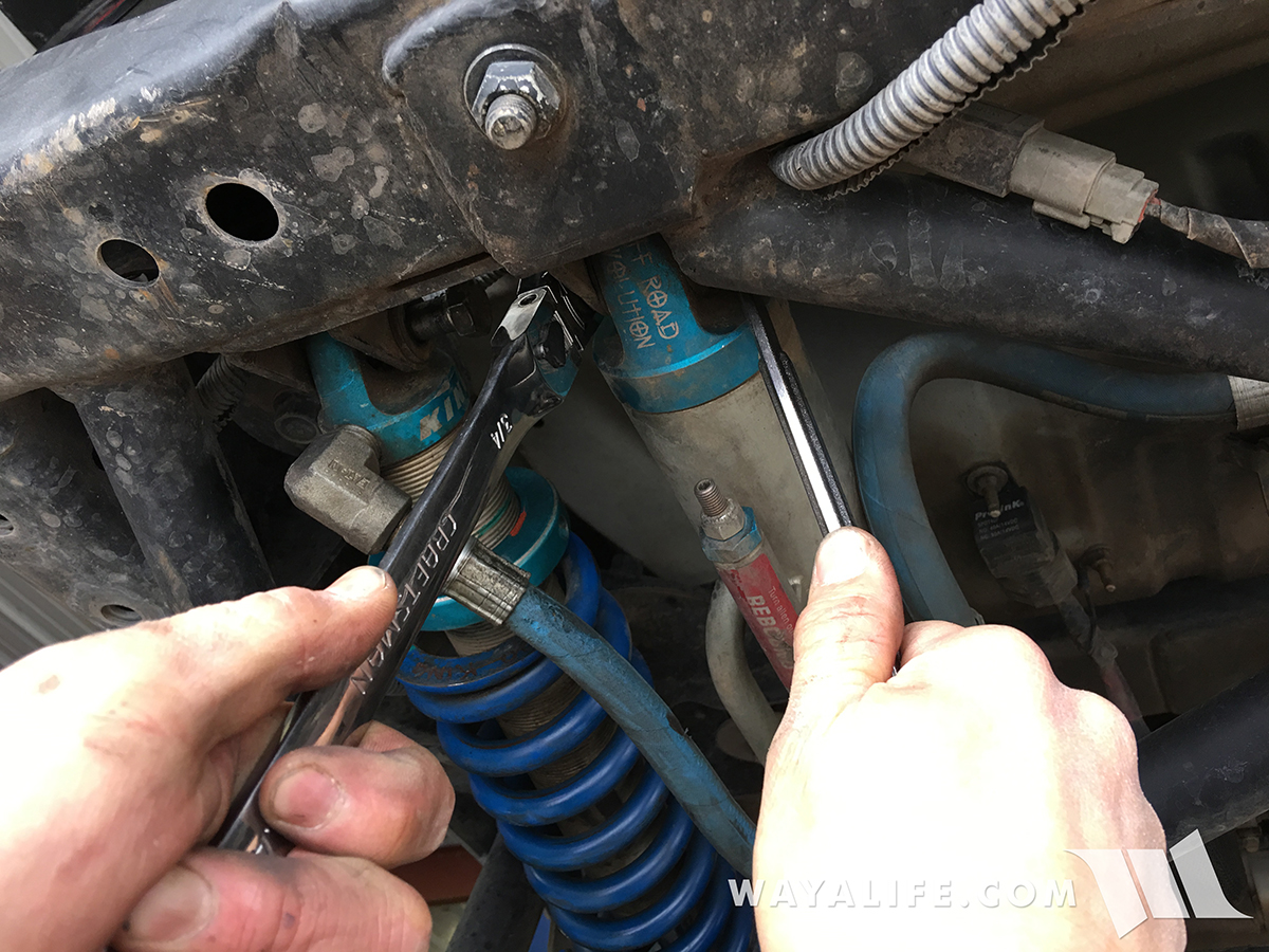
8. Again, you will need to use (2) 3/4" wrenches to remove the bolt, nut and washers securing your coil over to the EVO Lever frame as there is no room for a socket. A Gearwrench will help make this job easier.
9. As before, a pry bar may be needed to remove the coil over from the EVO Lever frame.
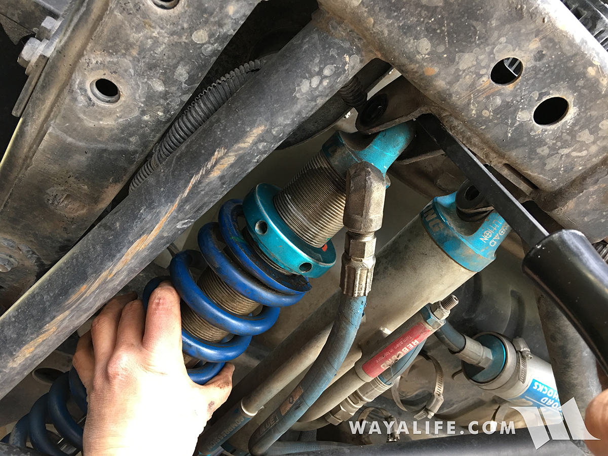
10. Use the pry bar again to remove your bypass shock.
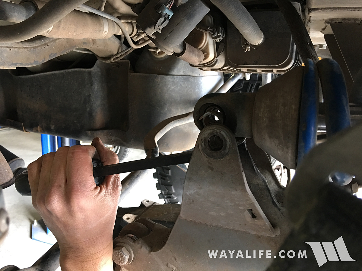
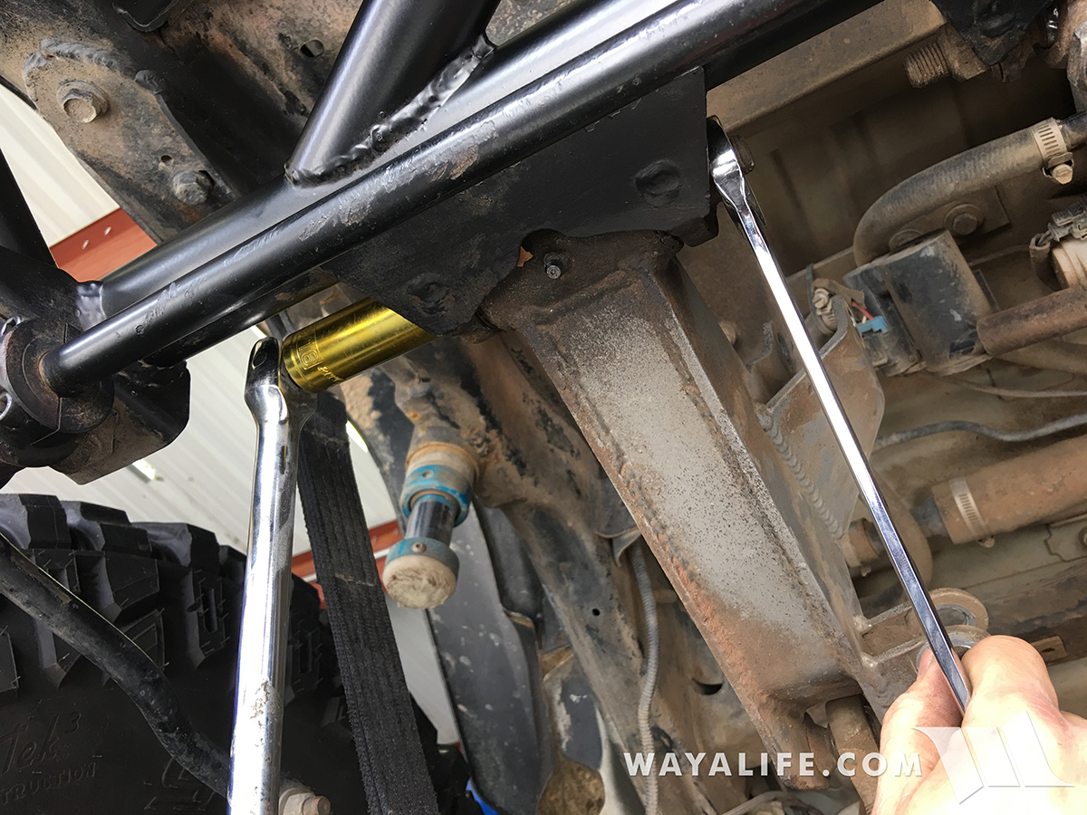
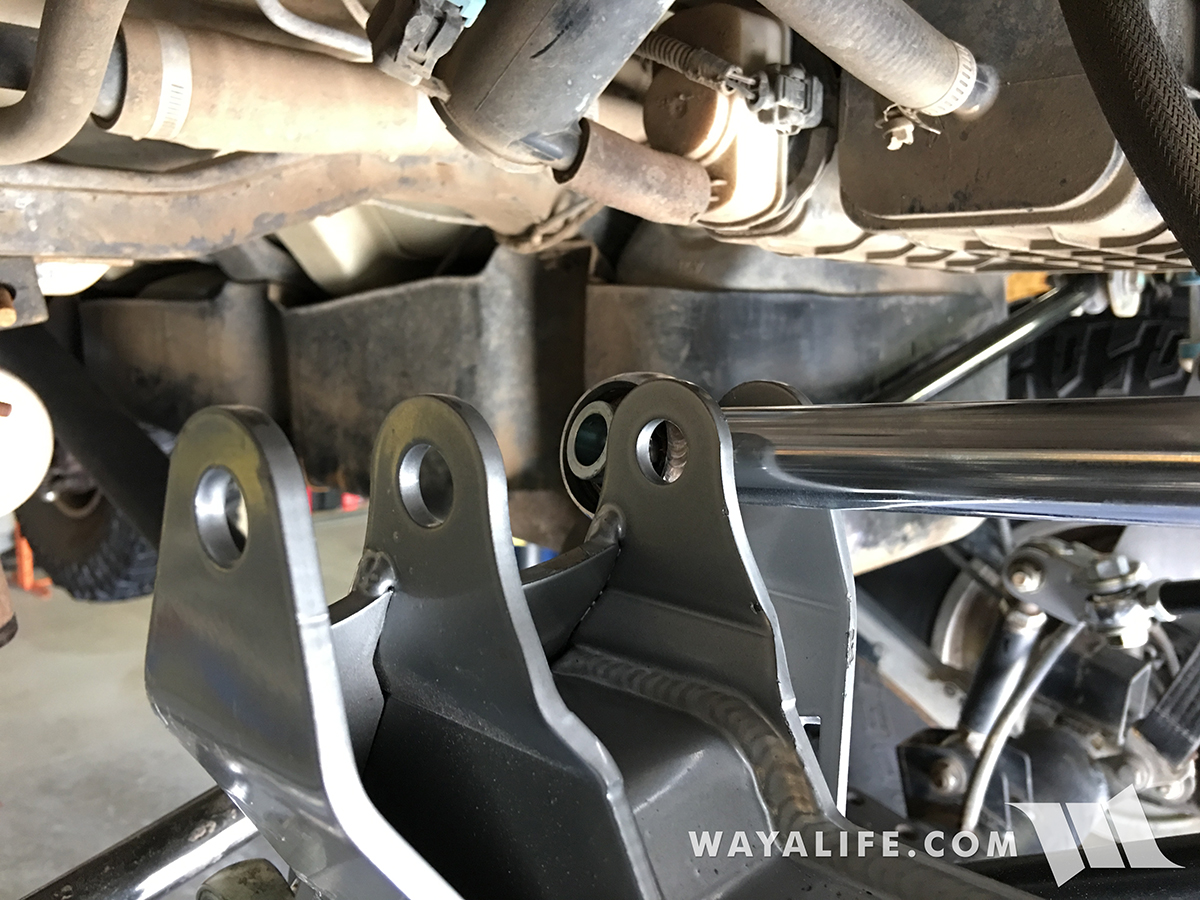
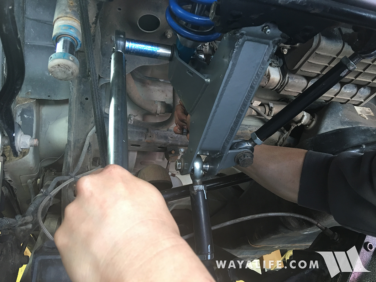
11. Using a 15/16" socket and wrench or crescent wrench, remove the bolt, nut and washers securing the support bar to the cantilever arm.
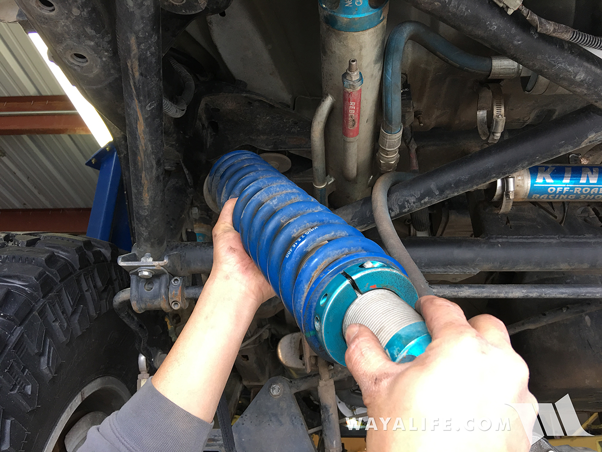
12. Using a 3/4" socket and 7/8" wrench, remove the bolt, nut and washers securing the axle link to the cantilever arm.
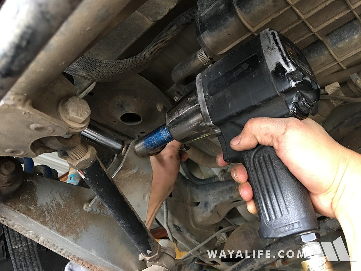
13. The bolt, nut and washers securing the pivot point of the cantilever arm to the EVO Lever frame will require the use of a breaker bar to free it. A 13/16" socket and 7/8" wrench will be needed for this job.
14. With the final bolt, nut and washers removed, you can now pull the cantilever arm out from under your Jeep and see just how bad a blown out pivot bushing looks like.
15. Repeat the steps above to remove the opposite side cantilever arm and then thoroughly inspect all your other heims and bushings and replace them as needed.
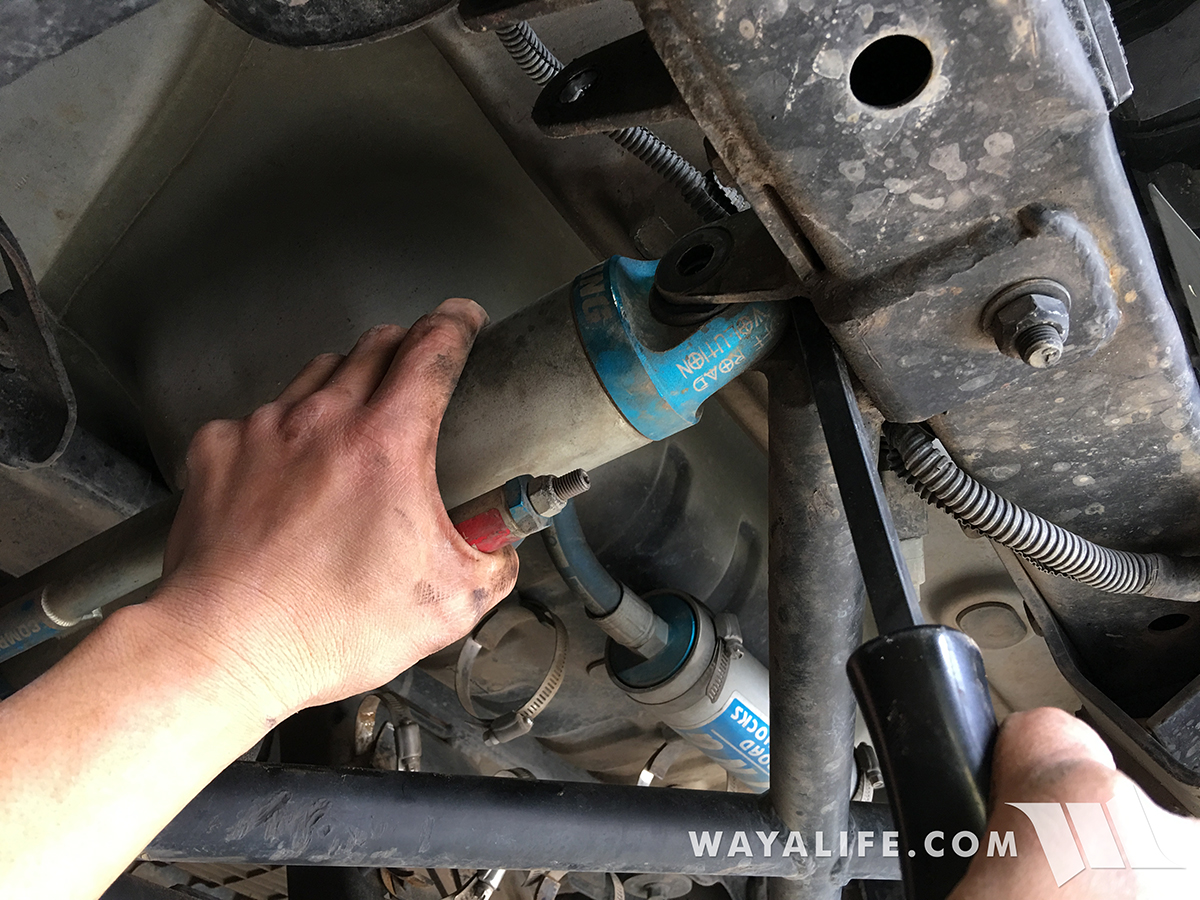
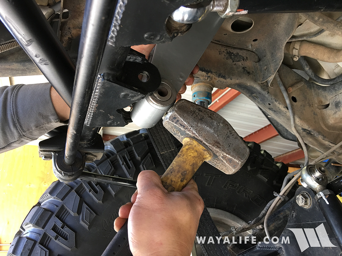
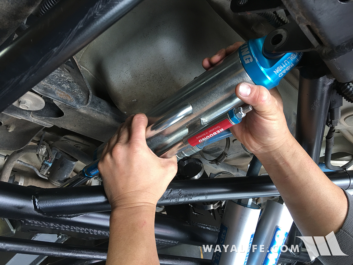
16. Getting the new cantilever arms installed on the EVO Lever pivot mount is a pain in the ass and you will need to help encourage it in with a big hammer.
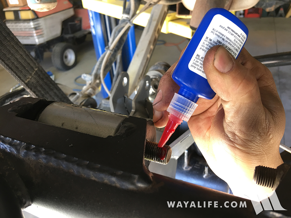
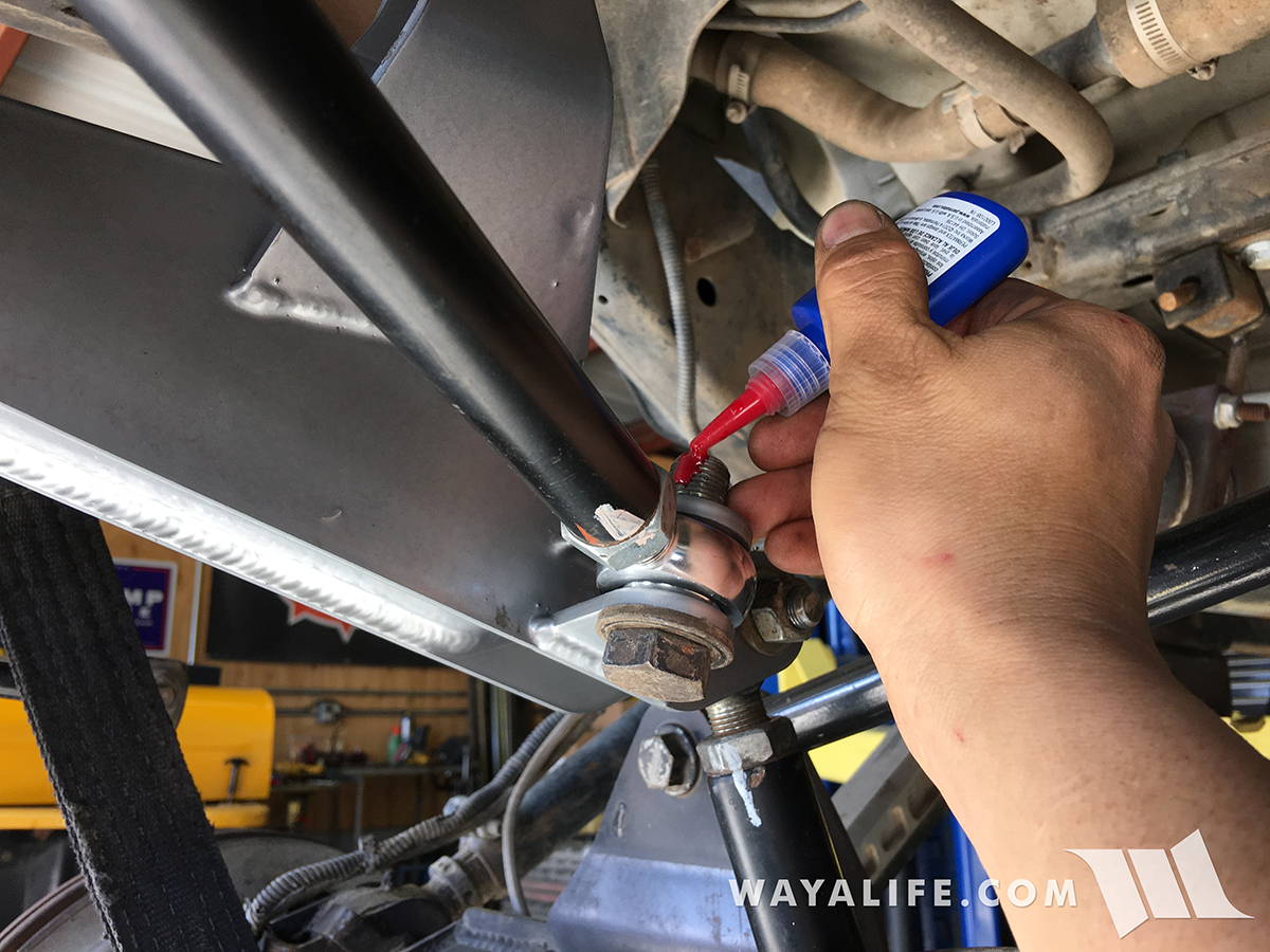
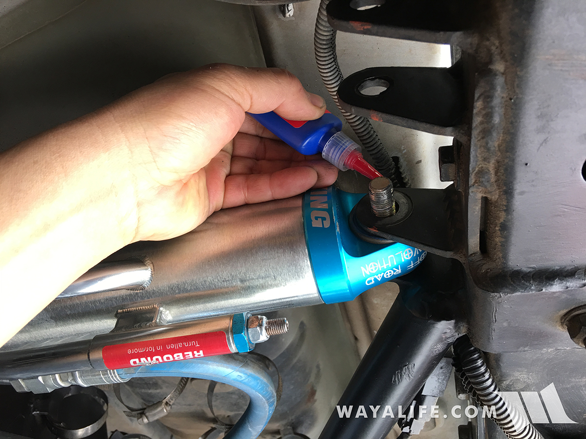
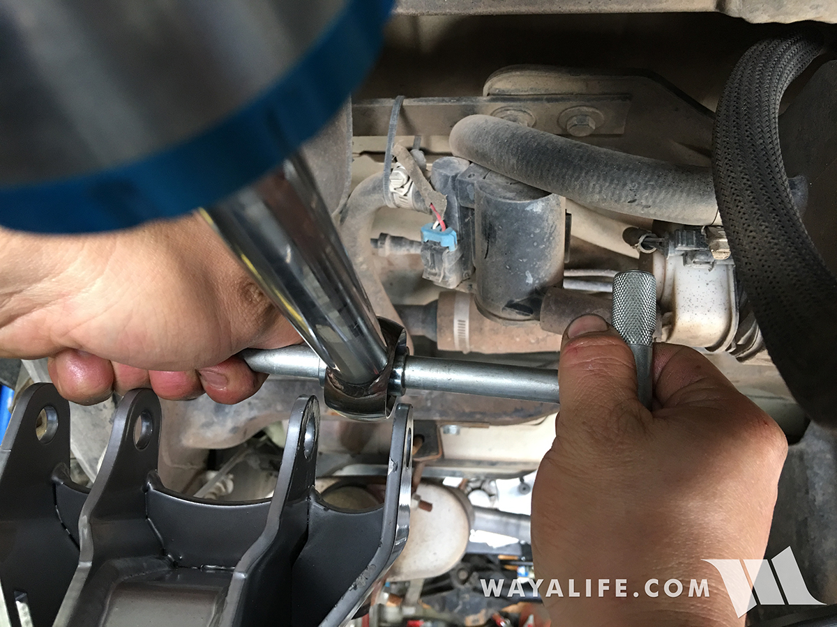
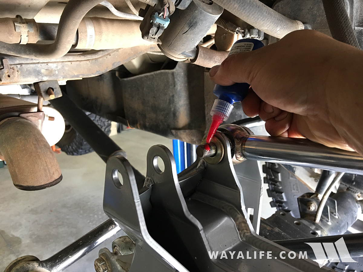
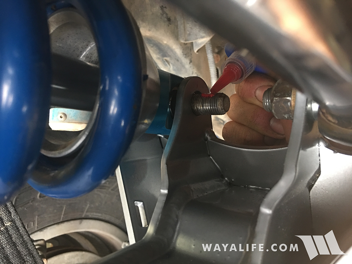
17. Insert the pivot mount bolt and washer an apply some red loc-tite to the threads.
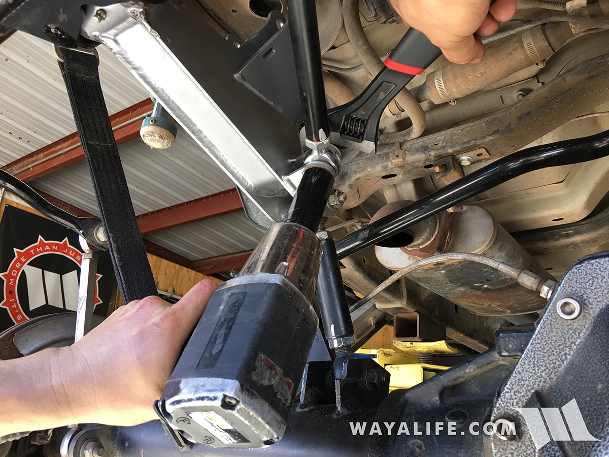
18. Using a 13/16" socket and 7/8" wrench, secure the cantilever arm to the EVO Lever pivot mount. Tighten the bolt and nut to 150-160 ft. lbs. of torque.
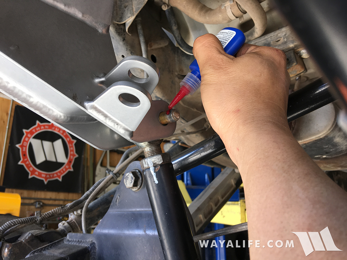
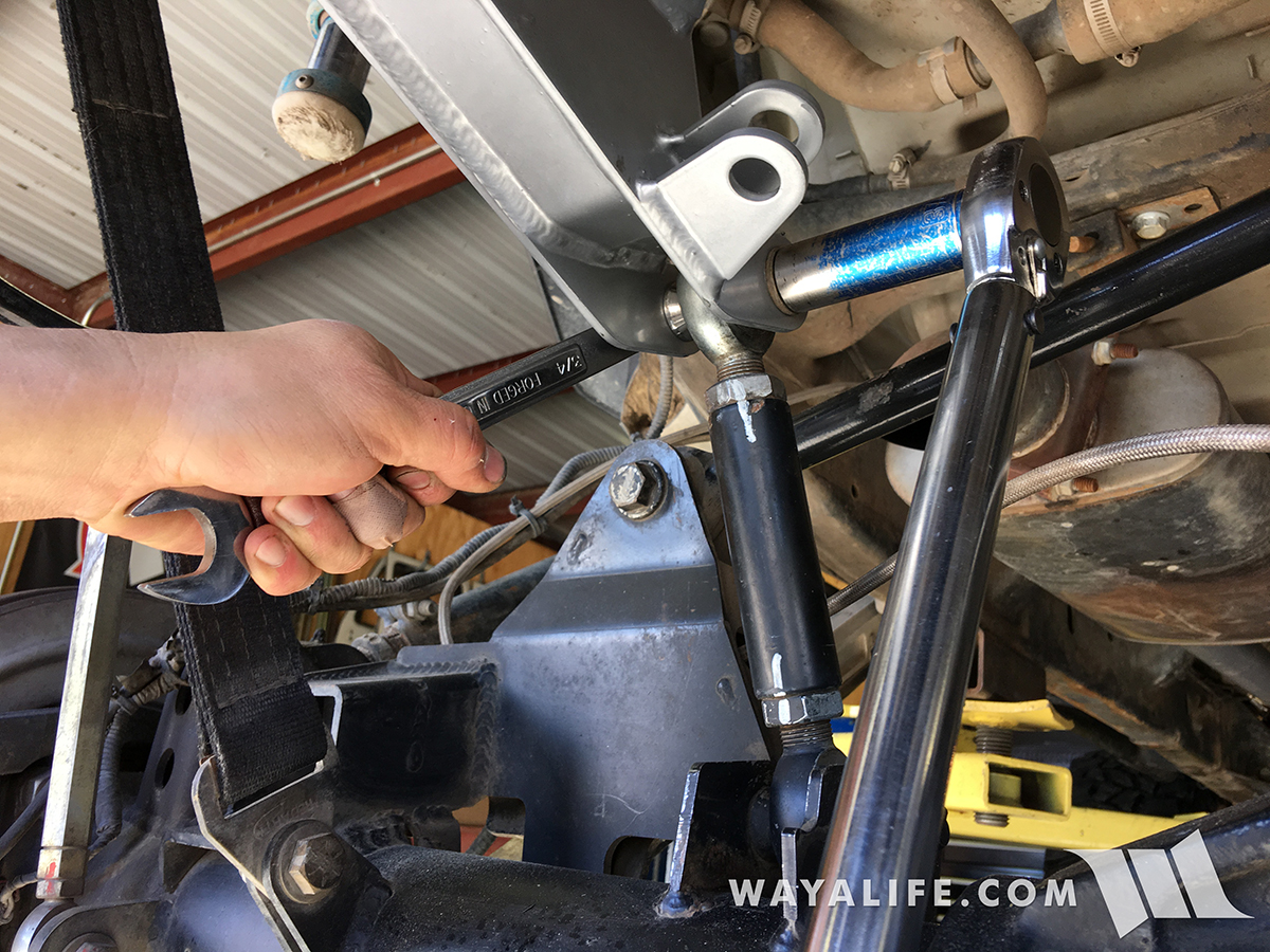
19. Attach the axle link to the cantilever arm, insert the bolt and washer to hold them together and then apply red loc-tite to the threads.
20. Using a 3/4" socket and 7/8" wrench, tighten the bolt and nut to 110-120 ft. lbs. of torque.
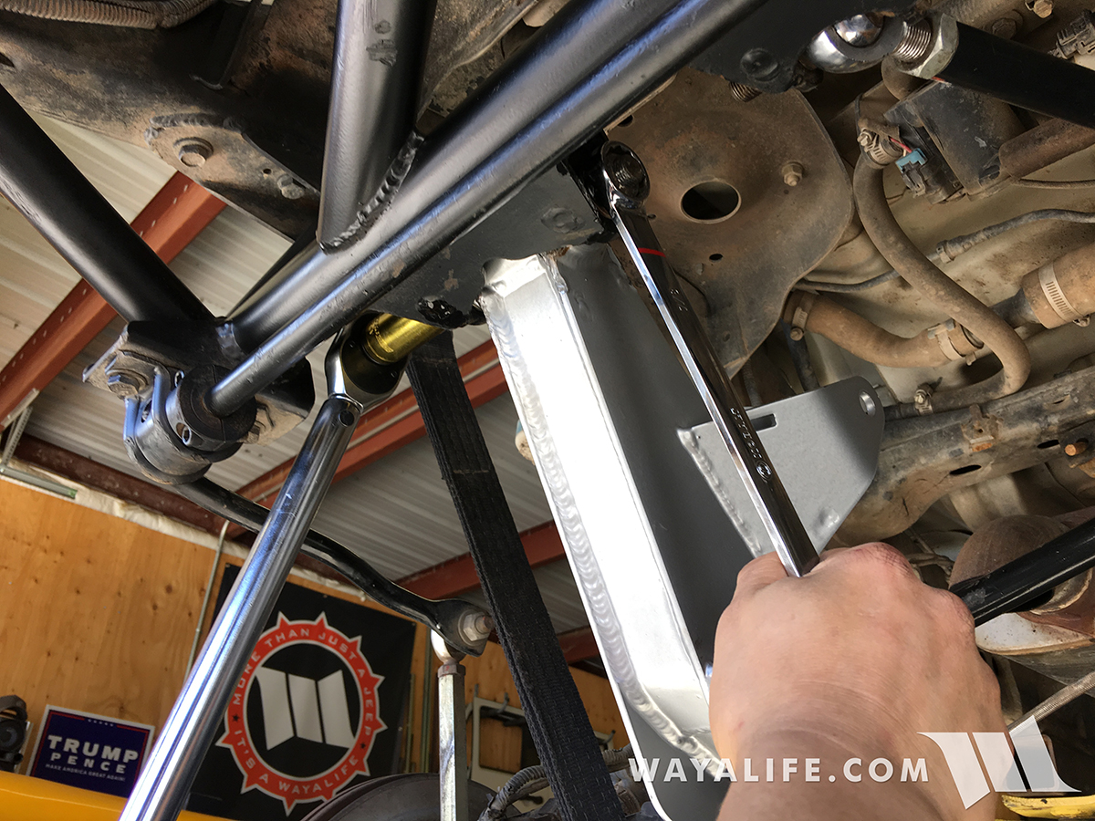
21. Attach the support bar to the cantilever arm, insert the bolt and washer to hold them together and then apply red loc-tite to the threads.
22. Using a 15/16" socket and wrench, tighten the support bar bolt and nut to 170-180 ft. lbs. of torque.
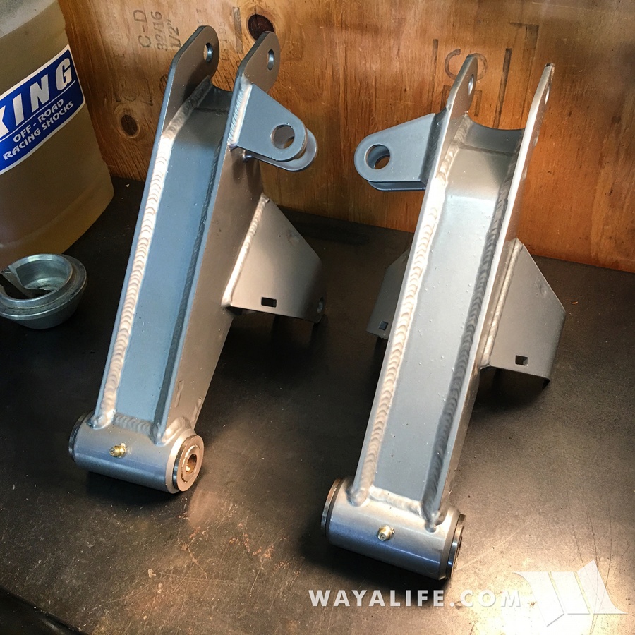
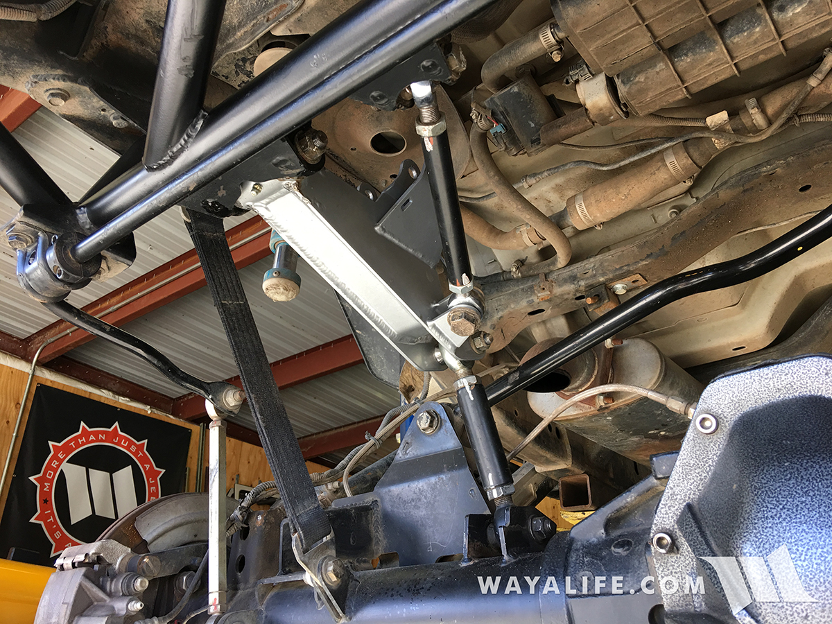
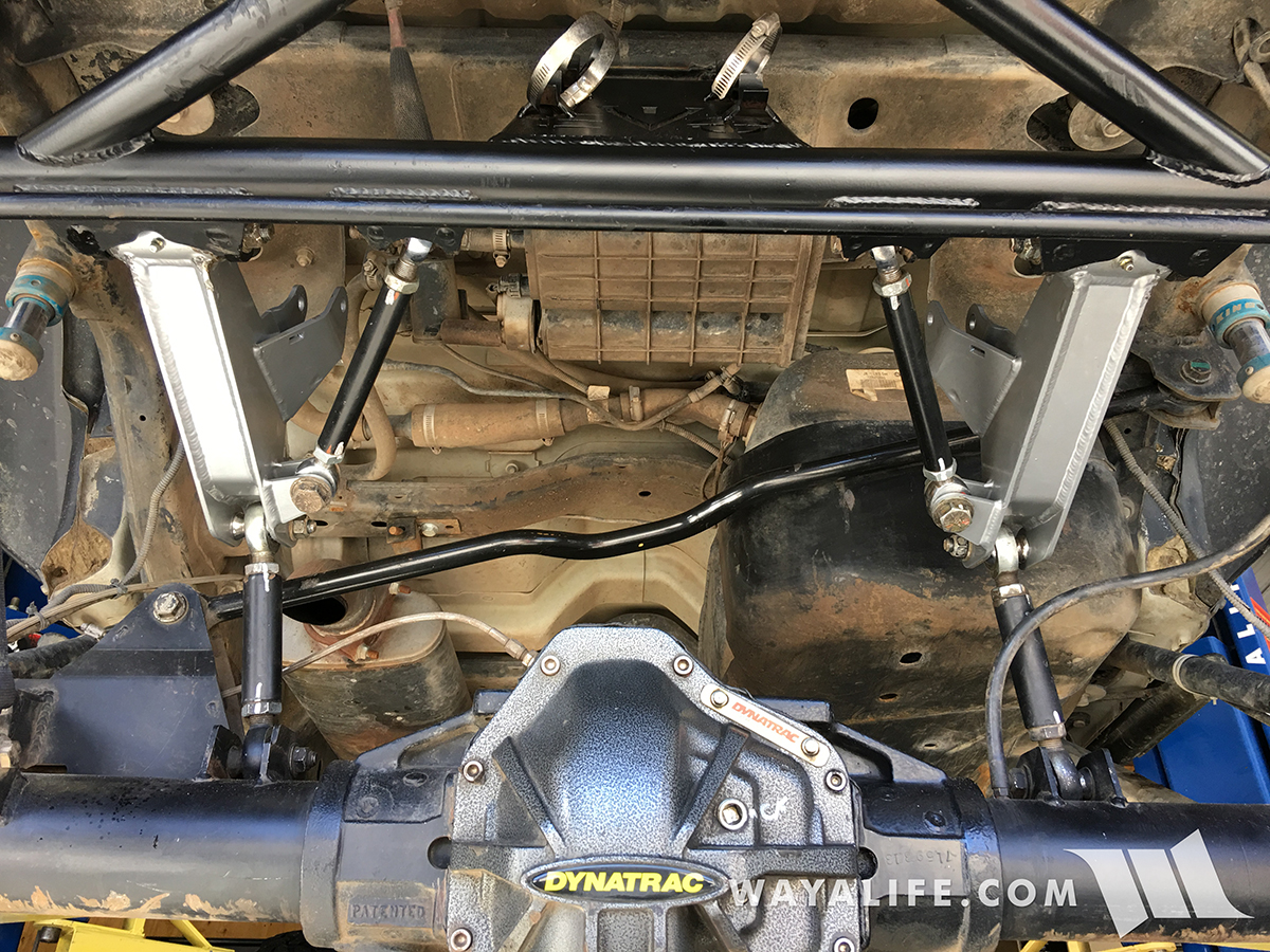
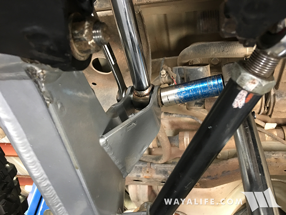
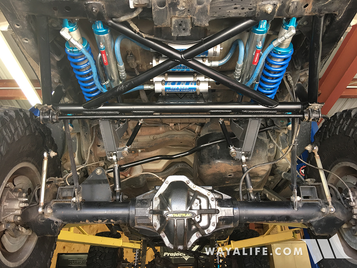
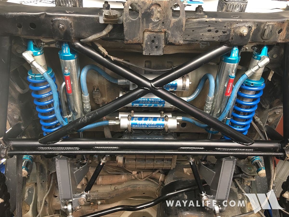
Here's a couple of shots of what the new cantilever arms look like installed.
For comparison sake, here's a side by shot of what the blown out pivot bushing looks like next to what it should look like.
For a while now, I've known that something was starting to get a bit off on the EVO Lever but I just was too busy wheeling and working on other Jeeps to take time out and address it. The first sign of something being wrong was an obnoxious squeaking that we'd get from time to time but it would always end up going away and that made it hard for me to keep looking for it. Recently, I started to hear an occasional but distinct clunk under acceleration that's when I knew I needed to give things a harder look. And, when I did, I noticed the following. To someone who's unfamiliar with what an EVO Cantilever arm should look like, this passenger side one is leaning and it shouldn't be.
It might might not look like much but for those who know what to look for, you'd know that the cantilever arm bushing here is blown.
Thinking that all we were going to need was a new bushing, we called up Mel to order up a new one but he recommended that it might be better to just replace both cantilever arm. With the amount of miles and abuse we've put them through, it would be the better way to go. Needless to say, that's what we did.
Because of the way the King coil over rod end is situated in the cantilever arm, it was difficult to do a good visual inspection of it and as I started to take things apart, I came across this. Some how, I don't think the spherical bearing is supposed to just fall out like this.
Here's a closer look at the rod end. As you can see, the spherical bearing of the heim had completely wore through it's housing. You can also see where the rod end itself has a grove cut into it from coming into contact with the cantilever arm.
You can also see how the small bearing spacers had dug into the cantilever arms and started to wear through.
Being that our cantilever arm swap just turned into a coil over rebuild as well, I decided to document the whole process and make a write-up out of it. For those of you who own a DTD and work on your own Jeep, I hope this will of some help to you.
What you will Need
(2)EVO DTD Cantilever Arms w/Bushings installed
(2) 2.0 PR Rod Ends 7/8 Thread Standard #21002-040
(2) Spherical Bearings 0.5 #B1012
(4) Retaining Rings, INT .500 BRG, 1.000 #CR2201
(4) 2.0 PR Bearing Spacers 1/2 x 1-1/4 #21017-001
• 3/4, 13/16, 7/8, 15/16" Socket & Wrench
• 3/4" Gearwrench
• 3/16" Allen Wrench
• Coil Over T-Handle Adjuster #25308-100 (2.0 & 2.5)
• Ratchet
• Torque Wrench
• Snap Ring Pliers
• Grease Gun
• Red Loc-Tite
• Pry Bar
• 5/16" Driver or Flathead Screwdriver
• Hammer
• Nitrogen
• Charging Manifold
• Cylinder Shaft Soft Jaw Clamp #100-001-(3/4”shaft)
• Shop Press
Instructions
1. After racking up your Jeep so that your rear tires are off the ground, measure the amount of pre-load you have on both your coil overs and make a note of it. Then, loosen the coil adjustment pinch bolt using a 3/16" allen wrench.
2. Use a coil over T-handle adjuster tool to loosen the coil adjustment nut until there's no longer a load on the coil.
3. Use a flathead screwdriver or 5/16" driver to loosen the hose clamps securing your coil over and bypass shock reservoirs to their mounts on the EVO Lever frame or bottom of your tub.
4. Using a 3/4" socket and wrench, remove the bolt, nut and washers securing the coil over to the cantilever arm.
5. You may find it necessary to use a pry bar to free the coil over rod end from the cantilever arm.
6. Using a 3/4" socket and wrench, remove the bolt, nut and washers securing the bypass shock to the cantilever arm.
7. You will need to use (2) 3/4" wrenches to remove the bolt, nut and washers securing your bypass shock to the EVO Lever frame as there is no room for a socket. A Gearwrench will help make this job easier.
8. Again, you will need to use (2) 3/4" wrenches to remove the bolt, nut and washers securing your coil over to the EVO Lever frame as there is no room for a socket. A Gearwrench will help make this job easier.
9. As before, a pry bar may be needed to remove the coil over from the EVO Lever frame.
10. Use the pry bar again to remove your bypass shock.
11. Using a 15/16" socket and wrench or crescent wrench, remove the bolt, nut and washers securing the support bar to the cantilever arm.
12. Using a 3/4" socket and 7/8" wrench, remove the bolt, nut and washers securing the axle link to the cantilever arm.
13. The bolt, nut and washers securing the pivot point of the cantilever arm to the EVO Lever frame will require the use of a breaker bar to free it. A 13/16" socket and 7/8" wrench will be needed for this job.
14. With the final bolt, nut and washers removed, you can now pull the cantilever arm out from under your Jeep and see just how bad a blown out pivot bushing looks like.
15. Repeat the steps above to remove the opposite side cantilever arm and then thoroughly inspect all your other heims and bushings and replace them as needed.
16. Getting the new cantilever arms installed on the EVO Lever pivot mount is a pain in the ass and you will need to help encourage it in with a big hammer.
17. Insert the pivot mount bolt and washer an apply some red loc-tite to the threads.
18. Using a 13/16" socket and 7/8" wrench, secure the cantilever arm to the EVO Lever pivot mount. Tighten the bolt and nut to 150-160 ft. lbs. of torque.
19. Attach the axle link to the cantilever arm, insert the bolt and washer to hold them together and then apply red loc-tite to the threads.
20. Using a 3/4" socket and 7/8" wrench, tighten the bolt and nut to 110-120 ft. lbs. of torque.
21. Attach the support bar to the cantilever arm, insert the bolt and washer to hold them together and then apply red loc-tite to the threads.
22. Using a 15/16" socket and wrench, tighten the support bar bolt and nut to 170-180 ft. lbs. of torque.
Here's a couple of shots of what the new cantilever arms look like installed.
For comparison sake, here's a side by shot of what the blown out pivot bushing looks like next to what it should look like.
")