Holeshot
Banned
I know Eddie already made one, but I went a different way for mounting the VCM and switch panel, And I think it may be interresting for some people looking for a different location for their switches.
So, I have ordered via email with Robert Muerrter, (who is the owner), a 6 switch panel, retailed at 325$. Customized the switches for the application I wanted.
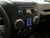
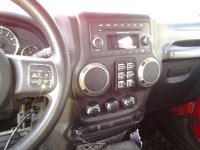
I got a 2012 with roll-up windows so I don't have the switches for the power windows. That leaves room for "small stuff" in the little compartment under the radio head unit, which isn't very practical and collect dust more than anything else. The 6 switch panel fits right there, so this is where I decided to install mine.
here we go with the install.
-----------------------------------------------------------
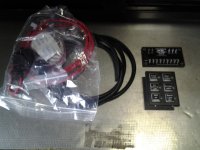
This is what you get in the package
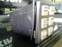
First of all, I had to find a way to attach the panel to the compartment. I had small 90 degree brackets left in my toolbox, which comes in mudflaps package we sell at the shop. They were a perfect fit for that purpose. I only had to trim the bottom of the lower brackets as they were rubbing on the bottom of the compartment.
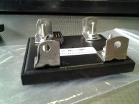
To remove the compartment, you can either use a small screw driver, or your bare hands. If using the screw driver, be carefull not to scratch the dash or leave small dents on it. Pry the top first, it should come off easily.
Once done with the fitment of the brackets, mark and drill the four holes (two per side), and clean the burrs on the inside. I used a step drill bit and an exacto knife to clean the burrs.
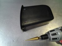
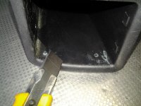
Then, I used four screws that have a flat head to clear and fit between the compartment and the dash, which also comes in the mudflap kit.
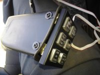
You will need to trim a little the edges to make room for the screws
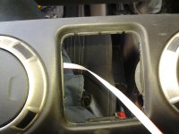
Once done, remove the panel and drill a hole where ever you want to route the logic wire throught it. I choosed to drill it on top. This way If I have to remove it for whatever reason, It's still gonna be usable. To route the logic cable, you gonna have to pop the top portion of the dash.
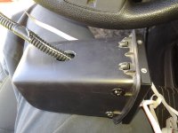
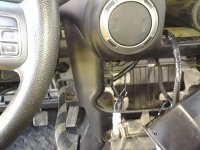
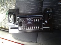
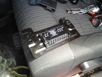
Now you need to find a location to put the VCM properly. It is written to place it on a clean, flat metal surface. You can either use the conductive tape on the back of the VCM, or screw it down in the four corners (of both if you want). The reason of this, is for heat dissipation, which help to cool down the VCM when under load. I choosed to install it under the steering column, for easy access if needed.
If you go the same route, you will have to remove the two screws that holds the plate, using a ratchet and 10mm socket. Then tape/screw the VCM to the plate. I decided to put it on the exterior, still for accessibility purpose.
Once the VCM installed and logic cable routed to the VCM location, make a loop with the extra lenght. Do not plug it at this time. It will be the last step.
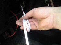
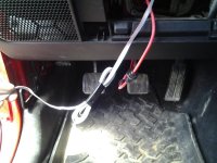
Now it's time to do the wiring! Do not plug any of the wire to the VCM at this point, until they are all ready to be plugued.
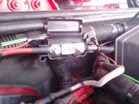
You will need to find a source that is on only when ignition is on. I already had my CB spliced to my 12V outlet in the dash (the one with the key drawn on it, that means it is powered when ignition is on) So I spliced a wire to my CB wire to get my IGN power. You will also need a known good ground. I used the one used by the factory wiring, found on the lower part of the dash, on the driver side. see picture
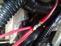
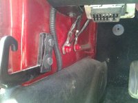
Now, route the main power wire from the battery to the VCM, do not plug it to the fuse holder until you're all done.
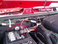
If you have a manual, you probably will need to drill a hole in the firewall. If you have an automatic, you can use the gromet on the left side of the brake booster. Use a hanger to pull the wire through. In my case, I drilled a hole on the right side of the brake booster, using a dremel and a carbide bit, and used a rubber gromet that was left in my toolbox.
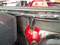
Next, start by pluging the ground wire to the VCM, on the GND terminal. Then the ignition 12v to the IGN terminal, and the 3 main power to the BAT terminals. Now you can plug the logic cable, and all the accessories you want.
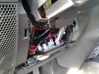
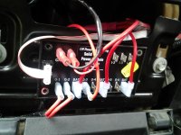
Then finally, plug the main power wire to the fuse holder.
And its time to test everything!
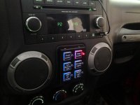
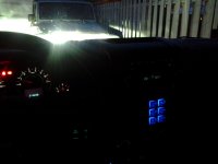
If you do it in the day, with a significant amount of light, make sure to see the blue back lighting of the switches, it is almost imperceptible during the day. If not sure, press a button and the red indicator will turn on.
Hope this help, if you have any question feel free to ask!
If you run into trouble for some reason, email Robert at ORE, he's a real good guy and will help you troubleshooting.
The first VCM I received was defect. The switch panel wasn't lighting up and not working. I then emailed Robert on saturday night, he replied on sunday morning and told me it was the first time it ever happened. We then troubleshooted everything by emails and concluded the VCM was defect. He then told me he would send me another one under warranty.
That said, I'm very happy with the product and the service Robert has given.
:standing wave:
Here's more pictures for the interrested.
So, I have ordered via email with Robert Muerrter, (who is the owner), a 6 switch panel, retailed at 325$. Customized the switches for the application I wanted.
I got a 2012 with roll-up windows so I don't have the switches for the power windows. That leaves room for "small stuff" in the little compartment under the radio head unit, which isn't very practical and collect dust more than anything else. The 6 switch panel fits right there, so this is where I decided to install mine.
here we go with the install.
-----------------------------------------------------------
This is what you get in the package

First of all, I had to find a way to attach the panel to the compartment. I had small 90 degree brackets left in my toolbox, which comes in mudflaps package we sell at the shop. They were a perfect fit for that purpose. I only had to trim the bottom of the lower brackets as they were rubbing on the bottom of the compartment.

To remove the compartment, you can either use a small screw driver, or your bare hands. If using the screw driver, be carefull not to scratch the dash or leave small dents on it. Pry the top first, it should come off easily.
Once done with the fitment of the brackets, mark and drill the four holes (two per side), and clean the burrs on the inside. I used a step drill bit and an exacto knife to clean the burrs.


Then, I used four screws that have a flat head to clear and fit between the compartment and the dash, which also comes in the mudflap kit.

You will need to trim a little the edges to make room for the screws

Once done, remove the panel and drill a hole where ever you want to route the logic wire throught it. I choosed to drill it on top. This way If I have to remove it for whatever reason, It's still gonna be usable. To route the logic cable, you gonna have to pop the top portion of the dash.


Now you need to find a location to put the VCM properly. It is written to place it on a clean, flat metal surface. You can either use the conductive tape on the back of the VCM, or screw it down in the four corners (of both if you want). The reason of this, is for heat dissipation, which help to cool down the VCM when under load. I choosed to install it under the steering column, for easy access if needed.
If you go the same route, you will have to remove the two screws that holds the plate, using a ratchet and 10mm socket. Then tape/screw the VCM to the plate. I decided to put it on the exterior, still for accessibility purpose.
Once the VCM installed and logic cable routed to the VCM location, make a loop with the extra lenght. Do not plug it at this time. It will be the last step.


Now it's time to do the wiring! Do not plug any of the wire to the VCM at this point, until they are all ready to be plugued.
You will need to find a source that is on only when ignition is on. I already had my CB spliced to my 12V outlet in the dash (the one with the key drawn on it, that means it is powered when ignition is on) So I spliced a wire to my CB wire to get my IGN power. You will also need a known good ground. I used the one used by the factory wiring, found on the lower part of the dash, on the driver side. see picture


Now, route the main power wire from the battery to the VCM, do not plug it to the fuse holder until you're all done.

If you have a manual, you probably will need to drill a hole in the firewall. If you have an automatic, you can use the gromet on the left side of the brake booster. Use a hanger to pull the wire through. In my case, I drilled a hole on the right side of the brake booster, using a dremel and a carbide bit, and used a rubber gromet that was left in my toolbox.

Next, start by pluging the ground wire to the VCM, on the GND terminal. Then the ignition 12v to the IGN terminal, and the 3 main power to the BAT terminals. Now you can plug the logic cable, and all the accessories you want.


Then finally, plug the main power wire to the fuse holder.

And its time to test everything!

If you do it in the day, with a significant amount of light, make sure to see the blue back lighting of the switches, it is almost imperceptible during the day. If not sure, press a button and the red indicator will turn on.
Hope this help, if you have any question feel free to ask!
If you run into trouble for some reason, email Robert at ORE, he's a real good guy and will help you troubleshooting.
The first VCM I received was defect. The switch panel wasn't lighting up and not working. I then emailed Robert on saturday night, he replied on sunday morning and told me it was the first time it ever happened. We then troubleshooted everything by emails and concluded the VCM was defect. He then told me he would send me another one under warranty.
That said, I'm very happy with the product and the service Robert has given.
:standing wave:
Here's more pictures for the interrested.


Last edited:

