PSC Power Steering Pump Bracket Failure **Old Version**

The other day, out of pure dumb luck, I happed to look at by PSC power steering pump and noticed my serpentine belt had slightly walked off of the pully and could see some black residue from the belt slightly rubbing somewhere. I tore into the Jeep and released the tension on the belt to remove it. I immediately noticed the power steering pump move/pivot a good amount and knew we had a problem.

This is on a 2014 Jeep JK Rubicon and installed this full PSC hydro assist kit approximately 5 years ago. I have had absolutely zero issues with it and still did not notice any unusual noise or performance issues. Knowing I had an issue and having OCD, I just ordered a new pump and a new bracket as I already new I had an older version.

After Removing the belt, high pressure line and return line, I was really able to see just how bad this was which you can see in this short clip.


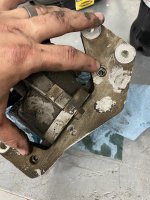
After removing the pump with the bracket, I noticed two of the four bolt heads were missing with the threads of the bolts still inside. (one of the bolt heads fell out as I pulled the pump). This is a two piece bracket. As I began to remove the high pressure line fitting on the old pump, the last bolts holding the bracket together broke. Needless to say, I couldn't have caught this at a better time and avoided a really bad day.

photo-apr-04-8-58-55-pm-jpg.373967


The bracket that was included with my original kit was the older style and should note that PSC has since updated the bracket which they weld on both sides along with four bolts. So if you recently installed a PSC kit, you should have the updated bracket.

Photo Apr 04, 10 26 52 PM.jpg

All better

Photo Apr 04, 9 31 52 PM (1).jpg

Note: This is also a good time to check and change your idler pulleys if needed.

PSC makes a great product and is great to see that they recognized and addressed this issue. If you have or think you might have the older style bracket, definitely something to keep an eye on to prevent a failure. The new bracket is a direct replacement if you decide to change yours from the older style.

Hope this helps!
 

Attachments

  • Photo Apr 04, 8 58 55 PM.jpg
    Photo Apr 04, 8 58 55 PM.jpg
    260 KB · Views: 168
I’d say that your “dumb luck” was very good luck! 😆 Seems odd that they didn’t do full welds on the new bracket though. I mean, a minute more and it would be way stronger, right?
 
I’d say that your “dumb luck” was very good luck! 😆 Seems odd that they didn’t do full welds on the new bracket though. I mean, a minute more and it would be way stronger, right?
The bolts still worked and did so for a while and, I’m sure there are plenty out there still that never had issues. The welds are definitely added strength and they do have welds on both sides.
 

kevman65

Hooked
Seems odd that they didn’t do full welds on the new bracket though. I mean, a minute more and it would be way stronger, right?

Not necessarily, might even cause more problems. The stress engineering for something like that is beyond my abused brain cell levels.

But too much weld can make the fixture warp in such a way that it takes strength away and makes bolt up difficult.
They calculate sheer strength, tensile strength, and LaZboy internet mechanic strength and come up with how many inches of weld over distance on the fitment. Plus they specify weld size, 1/4" 5/16" 3/8" for optimum strength.
Ah, that’s great info, thanks for explaining that out for me. I’m a beginner home welder and this the kind of stuff I like to learn. 👍
 

kevman65

Hooked
Ah, that’s great info, thanks for explaining that out for me. I’m a beginner home welder and this the kind of stuff I like to learn. 👍
In the picture above of the new, aluminum bracket. The weld you see is a fillet weld. It is a percentage of the thickness of the base metal wide. That is measured across the face, or top of the weld. In that picture it is hard to tell, but it is on appx a 45 degree angle.

Now someone took the thickness of the base material, both pieces, and figured the stresses across the weld, both shear and tensile. They plug that into a program (in the old days slide rules were involved) and it tells them how many inches of weld, how far from the ends and each other, and the size of the weld.

As a CWI (Certified Weld Inspector) all I concern myself with is the measurements of the welds and proper location. Which I would be given a sheet with those specs on it.

I've bitten my tongue on here several times, some people like to see the weld go around the corners, because sometimes that extra weld could be enough to cause the part to fail. We don't know what the engineers came up with when they ran their numbers. I understand the aesthetics of having the weld go around the corner, but there may a very good reason it wasn't done. That's if the manufacturer of the product did it themselves. I've dealt with a few DIY welding projects for vehicles before. They don't send you any welding specs, just a diagram and the parts.
Damn, I always assumed “more the better” and to insure there’s good penetration and little to no porosity… I had no idea there was that much math and science involved. I’ll be keeping my projects small for awhile. Lol. Thank you!
 

kevman65

Hooked
Damn, I always assumed “more the better” and to insure there’s good penetration and little to no porosity… I had no idea there was that much math and science involved. I’ll be keeping my projects small for awhile. Lol. Thank you!

The strength of the weld comes from the filler material. Be it stick rod for SMAW, filler wire for GTAW, or spooled wire for MIG.

For carbon steel, on GTAW or MIG, use an ER-70S wire. That wire is worth 70,000 pounds tensile strength. Base material should fail before weld.

You are correct, penetration and no porosity. For an open butt weld, you should have a bevel on at least one side, about 35 degrees, and a gap of 1/8" or a little smaller. If you get full penetration on that, then flush or a little higher than base metal and you're done. Anything more causes the base metal to start pulling at the top and causing it to weaken.

If you're using stick rod, 6010 (piping, root weld) is 60,000 pounds tensile strength. 7018 (piping, filler metal and cap) is 70,000 pounds tensile strength. Again, a little above flush of base material.

The other thing about at home welding, don't try to hurry the cool down, if anything you want it to take longer. If you blow air or dump water on a weld to cool it, you've made it brittle and induced micro-cracks into the metal. Once you're finished welding and cleaned it, wrap a fiberglass fire blanket or fiberglass insulation over the weld and base metal and walk away.
 
Last edited:
The strength of the weld comes from the filler material. Be it stick rod for SMAW, filler wire for GTAW, or spooled wire for MIG.

For carbon steel, on GTAW or MIG, use an ER-70S wire. That wire is worth 70,000 pounds tensile strength. Base material should fail before weld.

You are correct, penetration and no porosity. For an open butt weld, you should have a bevel on at least one side, about 35 degrees, and a gap of 1/8" or a little smaller. If you get full penetration on that, then flush or a little higher than base metal and you're done. Anything more causes the base metal to start pulling at the top and causing it to weaken.

If you're using stick rod, 6010 (piping, root weld) is 60,000 pounds tensile strength. 7018 (piping, filler metal and cap) is 70,000 pounds tensile strength. Again, a little above flush of base material.

The other thing about at home welding, don't try to hurry the cool down, if anything you want it to take longer. If you blow air or dump water on a weld to cool it, you're made it brittle and induced micro-cracks into the metal. Once you're finished welding and cleaned it, wrap a fiberglass fire blanket or fiberglass insulation over the weld and base metal and walk away.
Man, this is fantastic, thank you very much for that info. I do have a 110/220 mig and still have the initial spool of .030 flux core. Pretty soon I plan to switch to co2/argon gas and to .035 solid wire and will grab that er70s. I’m familiar with slow cooling, watched my fair share of “forged in fire”. Haha Have a few projects in mind. I’m debating on building my own rock sliders, should be a fun project. After that, I’d like to build a off-grid trailer; probably never will though since it’s a big job. 🤣. Thanks again, this was great. 👍
 

FRANKENCAR

New member
Thanks for posting this! When mine failed, I thought - this sure looks like poor design, then I fixed it. The burning question led to a search that led to this thread... Glad to know PSC isn't letting them out the door like the originals... Here's mine after extracting the broken bolts, replacing them and TIG welding it together so it won't do that again. IMG_3225.jpeg IMG_3226.jpeg IMG_3227.jpeg

Kind of a pain trying to get these old greasy parts clean enough to not contaminate the weld, and this isn't some pro stuff, but I'm sure it'll hold now.
 
Top Bottom